

Search results
Search for "CO2" in Full Text gives 333 result(s) in Beilstein Journal of Organic Chemistry. Showing first 200.
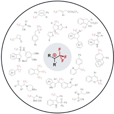
CF3-substituted carbocations: underexploited intermediates with great potential in modern synthetic chemistry
- Anthony J. Fernandes,
- Armen Panossian,
- Bastien Michelet,
- Agnès Martin-Mingot,
- Frédéric R. Leroux and
- Sébastien Thibaudeau
Beilstein J. Org. Chem. 2021, 17, 343–378, doi:10.3762/bjoc.17.32
- formation of allylic carbenium ions, such as 103 [81]. α-(Trifluoromethyl)alkynylcarbenium ions It has been reported that the complex of Co2(CO)6 and propargyl alcohols allows the facile generation of the corresponding propargylium ions (Nicholas reaction) in a relatively strong acidic medium (i.e., TFA

Graphical Abstract

Figure 1: Stabilizing interaction in the CF3CH2+ carbenium ion (top) and structure of the first observable fl...

Scheme 1: Isodesmic equations accounting for the destabilizing effect of the CF3 group. ΔE in kcal⋅mol−1, cal...

Scheme 2: Stabilizing effect of fluorine atoms by resonance electron donation in carbenium ions (δ in ppm).
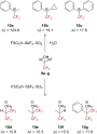
Scheme 3: Direct in situ NMR observation of α-(trifluoromethyl)carbenium ion or protonated alcohols. Δδ = δ19...

Scheme 4: Reported 13C NMR chemical shifts for the α-(trifluoromethyl)carbenium ion 10c (δ in ppm).
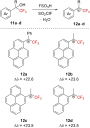
Scheme 5: Direct NMR observation of α-(trifluoromethyl)carbenium ions in situ (δ in ppm).

Scheme 6: Illustration of the ion pair solvolysis mechanism for sulfonate 13f. YOH = solvent.
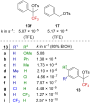
Figure 2: Solvolysis rate for 13a–i and 17.

Figure 3: Structures of allyl triflates 18 and 19 and allyl brosylate 20. Bs = p-BrC6H4SO2.

Figure 4: Structure of tosylate derivatives 21.
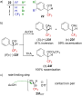
Figure 5: a) Structure of triflate derivatives 22. b) Stereochemistry outcomes of the reaction starting from (...

Scheme 7: Solvolysis reaction of naphthalene and anthracenyl derivatives 26 and 29.

Figure 6: Structure of bisarylated derivatives 34.

Figure 7: Structure of bisarylated derivatives 36.

Scheme 8: Reactivity of 9c in the presence of a Brønsted acid.
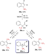
Scheme 9: Cationic electrocyclization of 38a–c under strongly acidic conditions.

Scheme 10: Brønsted acid-catalyzed synthesis of indenes 42 and indanes 43.

Scheme 11: Reactivity of sulfurane 44 in triflic acid.

Scheme 12: Solvolysis of triflate 45f in alcoholic solvents.

Scheme 13: Synthesis of labeled 18O-52.

Scheme 14: Reactivity of sulfurane 53 in triflic acid.

Figure 8: Structure of tosylates 56 and 21f.

Scheme 15: Resonance forms in benzylic carbenium ions.

Figure 9: Structure of pyrrole derivatives 58 and 59.

Scheme 16: Resonance structure 60↔60’.
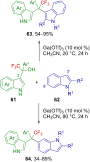
Scheme 17: Ga(OTf)3-catalyzed synthesis of 3,3’- and 3,6’-bis(indolyl)methane from trifluoromethylated 3-indol...

Scheme 18: Proposed reaction mechanism.

Scheme 19: Metal-free 1,2-phosphorylation of 3-indolylmethanols.
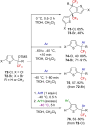
Scheme 20: Superacid-mediated arylation of thiophene derivatives.

Scheme 21: In situ mechanistic NMR investigations.
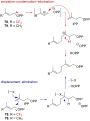
Scheme 22: Proposed mechanisms for the prenyltransferase-catalyzed condensation.

Scheme 23: Influence of a CF3 group on the allylic SN1- and SN2-mechanism-based reactions.

Scheme 24: Influence of the CF3 group on the condensation reaction.

Scheme 25: Solvolysis of 90 in TFE.

Scheme 26: Solvolysis of allyl triflates 94 and 97 and isomerization attempt of 96.

Scheme 27: Proposed mechanism for the formation of 95.

Scheme 28: Formation of α-(trifluoromethyl)allylcarbenium ion 100 in a superacid.
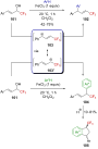
Scheme 29: Lewis acid activation of CF3-substituted allylic alcohols.
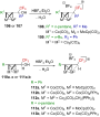
Scheme 30: Bimetallic-cluster-stabilized α-(trifluoromethyl)carbenium ions.
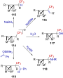
Scheme 31: Reactivity of cluster-stabilized α-(trifluoromethyl)carbenium ions.
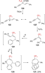
Scheme 32: α-(Trifluoromethyl)propargylium ion 122↔122’ generated from silyl ether 120 in a superacid.
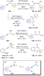
Scheme 33: Formation of α-(trifluoromethyl)propargylium ions from CF3-substituted propargyl alcohols.
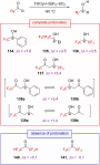
Scheme 34: Direct NMR observation of the protonation of some trifluoromethyl ketones in situ and the correspon...

Scheme 35: Selected resonance forms in protonated fluoroketone derivatives.

Scheme 36: Acid-catalyzed Friedel–Crafts reactions of trifluoromethyl ketones 143a,b and 147a–c.

Scheme 37: Enantioselective hydroarylation of CF3-substituted ketones.
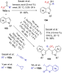
Scheme 38: Acid-catalyzed arylation of ketones 152a–c.

Scheme 39: Reactivity of 156 in a superacid.
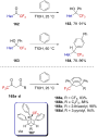
Scheme 40: Reactivity of α-CF3-substituted heteroaromatic ketones and alcohols as well as 1,3-diketones.

Scheme 41: Reactivity of 168 with benzene in the presence of a Lewis or Brønsted acid.

Scheme 42: Acid-catalyzed three-component asymmetric reaction.

Scheme 43: Anodic oxidation of amines 178a–c and proposed mechanism.
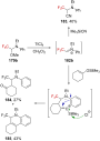
Scheme 44: Reactivity of 179b in the presence of a strong Lewis acid.

Scheme 45: Trifluoromethylated derivatives as precursors of trifluoromethylated iminium ions.

Scheme 46: Mannich reaction with trifluoromethylated hemiaminal 189.

Scheme 47: Suitable nucleophiles reacting with 192 after Lewis acid activation.
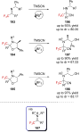
Scheme 48: Strecker reaction involving the trifluoromethylated iminium ion 187.
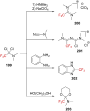
Scheme 49: Reactivity of 199 toward nucleophiles.

Scheme 50: Reactivity of 204a with benzene in the presence of a Lewis acid.

Scheme 51: Reactivity of α-(trifluoromethyl)-α-chloro sulfides in the presence of strong Lewis acids.

Scheme 52: Anodic oxidation of sulfides 213a–h and Pummerer rearrangement.

Scheme 53: Mechanism for the electrochemical oxidation of the sulfide 213a.

Scheme 54: Reactivity of (trifluoromethyl)diazomethane (217a) in HSO3F.

Figure 10: a) Structure of diazoalkanes 217a–c and b) rate-limiting steps of their decomposition.

Scheme 55: Deamination reaction of racemic 221 and enantioenriched (S)-221.

Scheme 56: Deamination reaction of labeled 221-d2. Elimination products were formed in this reaction, the yiel...
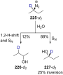
Scheme 57: Deamination reaction of 225-d2. Elimination products were also formed in this reaction in undetermi...

Scheme 58: Formation of 229 from 228 via 1,2-H-shift.

Scheme 59: Deamination reaction of 230. Elimination products were formed in this reaction, the yield of which ...

Scheme 60: Deamination of several diazonium ions. Elimination products were formed in these reactions, the yie...

Scheme 61: Solvolysis reaction mechanism of alkyl tosylates.

Scheme 62: Solvolysis outcome for the tosylates 248 and 249 in HSO3FSbF5.

Figure 11: Solvolysis rate of 248, 249, 252, and 253 in 91% H2SO4.

Scheme 63: Illustration of the reaction pathways. TsCl, pyridine, −5 °C (A); 98% H2SO4, 30 °C (B); 98% H2SO4, ...

Scheme 64: Proposed solvolysis mechanism for the aliphatic tosylate 248.

Scheme 65: Solvolysis of the derivatives 259 and 260.

Scheme 66: Solvolysis of triflate 261. SOH = solvent.

Scheme 67: Intramolecular Friedel–Crafts alkylations upon the solvolysis of triflates 264 and 267.

Scheme 68: α-CF3-enhanced γ-silyl elimination of cyclobutyltosylates 270a,b.
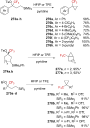
Scheme 69: γ-Silyl elimination in the synthesis of a large variety of CF3-substituted cyclopropanes. Pf = pent...

Scheme 70: Synthetic pathways to 281. aNMR yields.

Scheme 71: The cyclopropyl-substituted homoallylcyclobutylcarbenium ion manifold.
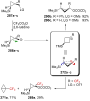
Scheme 72: Reactivity of CF3-substituted cyclopropylcarbinyl derivatives 287a–c. LG = leaving group.

Scheme 73: Reactivity of CF3-substituted cyclopropylcarbinyl derivatives 291a–c.

Scheme 74: Superacid-promoted dimerization or TFP.

Scheme 75: Reactivity of TFP in a superacid.
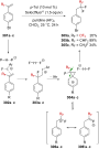
Scheme 76: gem-Difluorination of α-fluoroalkyl styrenes via the formation of a “hidden” α-RF-substituted carbe...

Scheme 77: Solvolysis of CF3-substituted pentyne 307.

Scheme 78: Photochemical rearrangement of 313.

Figure 12: Structure of 2-norbornylcarbenium ion 318 and argued model for the stabilization of this cation.

Figure 13: Structures and solvolysis rate (TFE, 25 °C) of the sulfonates 319–321. Mos = p-MeOC6H4SO2.

Scheme 79: Mechanism for the solvolysis of 323. SOH = solvent.

Scheme 80: Products formed by the hydrolysis of 328.

Scheme 81: Proposed carbenium ion intermediates in an equilibrium during the solvolysis of tosylates 328, 333,...
Selective synthesis of α-organylthio esters and α-organylthio ketones from β-keto esters and sodium S-organyl sulfurothioates under basic conditions
- Jean C. Kazmierczak,
- Roberta Cargnelutti,
- Thiago Barcellos,
- Claudio C. Silveira and
- Ricardo F. Schumacher
Beilstein J. Org. Chem. 2021, 17, 234–244, doi:10.3762/bjoc.17.24
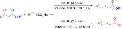
- place in β-keto esters, which is followed by CO2 displacement under heating [61][62][63][64]. We assume that in our case, when only 2 equiv of base are used, the keto–enol tautomer intermediates undergo a hydrolysis–decarboxylation process preferentially to a retro-Claisen reaction. This process forms

Graphical Abstract

Figure 1: Drugs and agrochemicals containing the α-thiocarbonyl core as a structural motif.

Scheme 1: Methods for the synthesis of α-thiocarbonyl compounds by C–C bond cleavage of 1,3-dicarbonyl compou...

Scheme 2: Formation of the enol 6 from acetylacetone (5).

Scheme 3: Formation of thio-substituted keto–enol tautomers 7 and 8.

Scheme 4: Proposed mechanism for the synthesis of 3.

Scheme 5: A tentative pathway for the synthesis of 4.
Insight into functionalized-macrocycles-guided supramolecular photocatalysis
- Minzan Zuo,
- Krishnasamy Velmurugan,
- Kaiya Wang,
- Xueqi Tian and
- Xiao-Yu Hu
Beilstein J. Org. Chem. 2021, 17, 139–155, doi:10.3762/bjoc.17.15
- activity (618.3 mmol⋅g−1⋅h−1) and an excellent stability (with a turnover number (TON) of 6417 after 75 h). Moreover, when the electron donor 1,3-dimethyl-2-phenyl-1,3-dihydrobenzimidazole (BIH) was added, the hybrid material functioned as an efficient photocatalyst for the reduction of CO2 to CO with 0.26
- (c) EY. Republished with permission of The Royal Society of Chemistry from [30] (“Host–guest chemistry between cyclodextrin and a hydrogen evolution catalyst cobaloxime” by M. Kato et al., New J. Chem. vol. 43, © 2019); permission conveyed through Copyright Clearing Center, Inc. Conversion of CO2 to

Graphical Abstract

Figure 1: Chemical structures of representative macrocycles.

Figure 2: Ba2+-induced intermolecular [2 + 2]-photocycloaddition of crown ether-functionalized substrates 1 a...

Figure 3: Energy transfer system constructed of a BODIPY–zinc porphyrin–crown ether triad assembly bound to a...

Figure 4: The sensitizer 5 was prepared by a flavin–zinc(II)–cyclen complex for the photooxidation of benzyl ...

Figure 5: Enantiodifferentiating Z–E photoisomerization of cyclooctene sensitized by a chiral sensitizer as t...

Figure 6: Structures of the modified CDs as chiral sensitizing hosts. Adapted with permission from [24], Copyrigh...
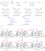
Figure 7: Supramolecular 1:1 and 2:2 complexations of AC with the cationic β-CD derivatives 16–21 and subsequ...

Figure 8: Construction of the TiO2–AuNCs@β-CD photocatalyst. Republished with permission of The Royal Society...

Figure 9: Visible-light-driven conversion of benzyl alcohol to H2 and a vicinal diol or to H2 and benzaldehyd...

Figure 10: (a) Structures of CDs, (b) CoPyS, and (c) EY. Republished with permission of The Royal Society of C...

Figure 11: Conversion of CO2 to CO by ReP/HO-TPA–TiO2. Republished with permission of The Royal Society of Che...

Figure 12: Thiacalix[4]arene-protected TiO2 clusters for H2 evolution. Reprinted with permission from [37], Copyri...

Figure 13: 4-Methoxycalix[7]arene film-based TiO2 photocatalytic system. Reprinted from [38], Materials Today Chem...

Figure 14: (a) Photodimerization of 6-methylcoumarin (22). (b) Catalytic cycle for the photodimerization of 22...

Figure 15: Formation of a supramolecular PDI–CB[7] complex and structures of monomers and the chain transfer a...

Figure 16: Ternary self-assembled system for photocatalytic H2 evolution (a) and structure of 27 (b). Figure 16 reprodu...
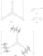
Figure 17: Structures of COP-1, CMP-1, and their substrate S-1 and S-2.

Figure 18: Supramolecular self-assembly of the light-harvesting system formed by WP5, β-CAR, and Chl-b. Reprod...

Figure 19: Photocyclodimerization of AC based on WP5 and WP6.
The fluorescence of a mercury probe based on osthol
- Guangyan Luo,
- Zhishu Zeng,
- Lin Zhang,
- Zhu Tao and
- Qianjun Zhang
Beilstein J. Org. Chem. 2021, 17, 22–27, doi:10.3762/bjoc.17.3
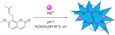
- performance of fluorescent probes. As shown in Figure 1A, the selectivity of OST to common metal ions is monitored by the fluorescence spectrum (λex = 325 nm). OST exhibits a weak fluorescence intensity at λex = 406 nm. When adding different metal ions (Hg2+, Ca2+, Na+, Mg2+, Al3+, Cd2+, Cu2+, Pb2+, Ni2+, Co2

Graphical Abstract

Figure 1: (A) Fluorescence spectra of OST (c = 3.0 × 10⁻⁵ mol∙L−1) upon the addition of various metal ions. (...

Figure 2: Metal ion selectivity of OST–Hg2+ (c = 3.0 × 10⁻⁵ mol∙L−1) in the presence of 1.2 × 10⁻⁴ mol∙L−1 of...

Figure 3: Fluorescence spectra of OST (c = 3 × 10⁻⁵ mol∙L−1) in H2O/CH3OH 97:3, v/v in the presence of an inc...

Figure 4: The standard Job curve of mercury ions to OST (c = 3.0 × 10⁻⁵ mol∙L−1) at 406 nm (pH 7.0, H2O/CH3OH...

Figure 5: Mass spectrum of the probe with Hg2+.

Figure 6: 1H NMR titration spectra recorded for OST (c = 5 × 10⁻⁴ mol∙L−1) during the addition of different m...

Figure 7: The binding mode of OST and Hg2+.
Controlled decomposition of SF6 by electrochemical reduction
- Sébastien Bouvet,
- Bruce Pégot,
- Stéphane Sengmany,
- Erwan Le Gall,
- Eric Léonel,
- Anne-Marie Goncalves and
- Emmanuel Magnier
Beilstein J. Org. Chem. 2020, 16, 2948–2953, doi:10.3762/bjoc.16.244
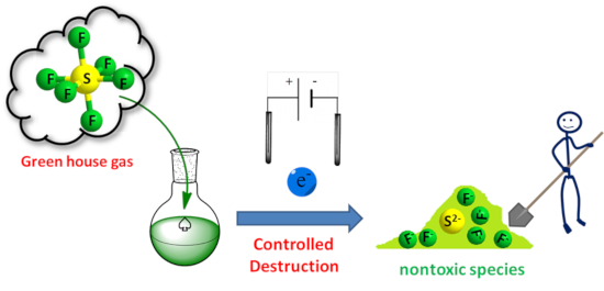
- ][7]. On the other hand, SF6 is a greenhouse gas [8]. It has indeed a global warming potential (GWP) 22,000 times greater than CO2 [9]. From an industrial point of view, this requires efficient methods of recycling or destroying SF6. This last point implies, because of its great stability, the use of

Graphical Abstract

Figure 1: (a) Cyclic voltammetry onto microelectrode arrays (Ø = 20 µm) in acetonitrile freshly distilled aft...

Figure 2: Variation of the current reduction (i2) of SF6 onto Pt macroelectrode (Ø = 0.76 mm) at −2.3 V vs Fc+...

Figure 3: Single compartment three-electrode experiment. 1: Balloon of SF6, 2: electrochemical cell, 3: refer...

Figure 4: Electrolysis of SF6 at −2.3 V vs Fc+/Fc in acetonitrile freshly distilled after addition of TBAClO4...

Figure 5: 19F NMR evolution of the crude mixture along the time after electrolysis realized at constant poten...
Dawn of a new era in industrial photochemistry: the scale-up of micro- and mesostructured photoreactors
- Emine Kayahan,
- Mathias Jacobs,
- Leen Braeken,
- Leen C.J. Thomassen,
- Simon Kuhn,
- Tom van Gerven and
- M. Enis Leblebici
Beilstein J. Org. Chem. 2020, 16, 2484–2504, doi:10.3762/bjoc.16.202
- has already been proven to be successful [4]. These examples show that photochemistry is a viable alternative to conventional chemistry approaches. In addition to specialty chemicals and wastewater treatment, photochemical pathways can also be used for methanol production [5], N2 fixation [6], and CO2
- photoreactor. The main reasons for this increase was the high surface-area-to-volume ratio and better illumination of the monolithic photoreactor [56]. The monolithic photoreactor was shown to have a higher yield for the CO2 photoreduction compared to a cell-type reactor that had no channels. This was

Graphical Abstract

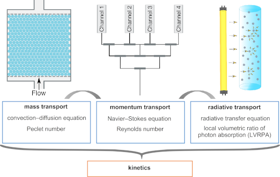
Figure 1: The momentum transport affects the mass transfer and the light field. All transport phenomena need ...

Figure 2: Common photomicroreactor designs: (a) Straight channel, (b) serpentine channel, (c) square serpenti...

Figure 3: Benchmarked photoreactors: (a) Microcapillaries in parallel, (b) microcapillaries in series, (c) fl...
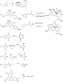
Figure 4: Photochemical reactions that are detailed in Table 1.

Figure 5: Structured reactors designed for enhancing the mass transfer: (a) Packed bed photoreactor, (b) mono...

Figure 6: Comparison of the LED board designs of photomicroreactors: (a) CC array design, (b) MC array design...

Figure 7: Illustration of the light scattering phenomenon inside a photocatalytic flow reactor.

Figure 8: Efficiency of the absorption process in scattering situations with respect to pure absorption situa...

Figure 9: Different types of distributors: (a) Traditional or consecutive manifold, (b) bifurcation unit dist...
The B & B approach: Ball-milling conjugation of dextran with phenylboronic acid (PBA)-functionalized BODIPY
- Patrizia Andreozzi,
- Lorenza Tamberi,
- Elisamaria Tasca,
- Gina Elena Giacomazzo,
- Marta Martinez,
- Mirko Severi,
- Marco Marradi,
- Stefano Cicchi,
- Sergio Moya,
- Giacomo Biagiotti and
- Barbara Richichi
Beilstein J. Org. Chem. 2020, 16, 2272–2281, doi:10.3762/bjoc.16.188
- ). The cells were maintained at 37 °C, with 5% CO2 in a humidified chamber. Cell viability MTT assay Cell mitochondrial activity was tested using the 3-(4,5-dimethylthiazol-2-yl)-2,5-diphenyltetrazolium bromide (MTT) assay, which is based on the mitochondrial conversion of the tetrazolium salt into a

Graphical Abstract

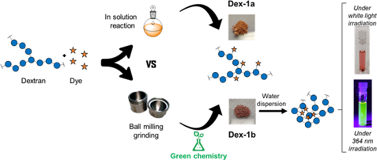
Figure 1: Structure of PBA-BODIPY (1) and schematic representation of dextran (Dex) and PBA-BODIPY conjugated...

Scheme 1: Schematic representation of dextran/PBA-BODIPY bioconjugations in: A. conventional solution-based c...

Figure 2: A) Amount of recovered PBA-BODIPY (1, i.e., nonreacted 1) in the mixtures DMSO/EtOH and in the seri...

Figure 3: A) UV–vis absorption and B) fluorescence emission spectra (λexc = 380 nm) of the BODIPY-dextran con...

Figure 4: A) Hydrodynamic diameter of (nm) conjugate Dex-1b (at 1 mg/mL in H2O, black curve) and PBS (red cur...

Figure 5: Fluorescence emission spectra of pyrene (4.4 × 10⁻⁸ M) in water and in a water solution in the pres...
Synthetic approaches to bowl-shaped π-conjugated sumanene and its congeners
- Shakeel Alvi and
- Rashid Ali
Beilstein J. Org. Chem. 2020, 16, 2212–2259, doi:10.3762/bjoc.16.186
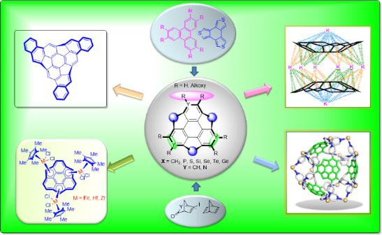
- thermoelectric properties in addition to the onigiri-type core-shell assemblies have been reported for sumanene and its derivatives. More interestingly, its application in the absorption of small molecules such as NH3, CO2, CO, and H2 using density functional theory (DFT) calculations has also been revealed [25

Graphical Abstract
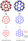
Figure 1: Representation of corannulene (1) and sumanene (2), the subunits of fullerene (C60).

Scheme 1: Mehta’s unsuccessful effort for the synthesis of sumanene scaffold 2.

Scheme 2: First synthesis of sumanene 2 by Sakurai et al. from norbornadiene 10.

Scheme 3: Synthesis of trimethylsumanene 28 from easily accessible norbornadiene (10).

Scheme 4: Generation of anions 29–31 and the preparation of tris(trimethylsilyl)sumanene 32.

Scheme 5: Synthesis of tri- and hexa-substituted sumanene derivatives.

Scheme 6: Synthesis of bowl-shaped π-extended sumanene derivatives 37a–f.

Scheme 7: Synthesis of monooxasumanene 38, trioxosumanene 40 along with imination of them.

Scheme 8: Synthesis of trimethylsumanenetrione 46 and exo-functionalized products 45a,b.

Scheme 9: Synthesis of bisumanenylidene 47 and sumanene dimer 48 from 2.

Scheme 10: The mono-substitution of 2 to generate diverse mono-sumanene derivatives 49a–d.

Scheme 11: Synthesis of sumanene building block 53 useful for further extension.

Scheme 12: Synthesis of hexafluorosumanene derivative 55 by Sakurai and co-workers.

Scheme 13: Preparation of sumanene-based carbene 60 and its reaction with cyclohexane.

Scheme 14: Barton–Kellogg reaction for the synthesis of sterically hindered alkenes.

Scheme 15: Synthesis of hydroxysumanene 68 by employing Baeyer–Villiger oxidation.

Scheme 16: Synthesis of sumanene derivatives having functionality at an internal carbon.

Scheme 17: Mechanism for nucleophilic substitution reaction at the internal carbon.

Scheme 18: Synthesis of diverse monosubstituted sumanene derivatives.
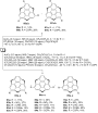
Scheme 19: Synthesis of di- and trisubstituted sumanene derivatives from sumanene (2).

Scheme 20: Preparation of monochlorosumanene 88 and hydrogenation of sumanene (2).

Scheme 21: The dimer 90 and bissumanenyl 92 achieved from halosumannes.

Scheme 22: Pyrenylsumanene 93 involving the Suzuki-coupling as a key transformation.
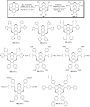
Scheme 23: Synthesis of various hexaarylsumanene derivatives using the Suzuki-coupling reaction.

Scheme 24: Synthesis of hexasubstituted sumanene derivatives 96 and 97.

Scheme 25: Synthesis of thioalkylsumanenes via an aromatic nucleophilic substitution reaction.

Scheme 26: Synthesis of tris(ethoxycarbonylethenyl)sumanene derivative 108.
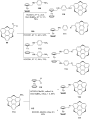
Scheme 27: Synthesis of ferrocenyl-based sumanene derivatives.

Scheme 28: Synthesis of sumanenylferrocene architectures 118 and 119 via Negishi coupling.

Scheme 29: Diosmylation and the synthesis of phenylboronate ester 121 of sumanene.

Scheme 30: Synthesis of the iron-complex of sumanene.

Scheme 31: Synthesis of tri- and mononuclear sumanenyl zirconocene complexes.

Scheme 32: Synthesis of [CpRu(η6-sumanene)]PF6.

Scheme 33: Preparation of sumanene-based porous coordination networks 127 (spherical tetramer units) and 128 (...

Scheme 34: Synthesis of sumanenylhafnocene complexes 129 and 130.

Scheme 35: Synthesis of 134 and 135 along with PdII coordination complex 136.

Scheme 36: Synthesis of alkali metals sumanene complex K7(C21H102−)2(C21H93−)·8THF (137) containing di- and tr...

Scheme 37: The encapsulation of a Cs+ ion between two sumanenyl anions.

Scheme 38: Synthesis of monothiasumanene 140 and dithiasumanene 141 from 139.

Scheme 39: Synthesis of trithiasumanene 151 by Otsubo and his co-workers.

Scheme 40: Synthesis of trithiasumanene derivatives 155 and 156.

Scheme 41: Synthetic route towards hexathiolated trithiasumanenes 158.

Scheme 42: Synthesis of triselenasumanene 160 by Shao and teammates.

Scheme 43: Synthesis of tritellurasumanene derivatives from triphenylene skeletons.
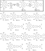
Scheme 44: Synthesis of pyrazine-fused sumanene architectures through condensation reaction.

Scheme 45: Treatment of the trichalcogenasumanenes with diverse oxidative reagents.

Scheme 46: Ring-opening reaction with H2O2 and oxone of heterasumanenes 178 and 179.

Scheme 47: Synthesis of polycyclic compounds from sumanene derivatives.

Scheme 48: Synthesis of diimide-based heterocycles reported by Shao’s and co-workers.

Scheme 49: Synthesis of pristine trichalcogenasumanenes, 151, 205, and 206.

Scheme 50: Synthesis of trichalcogenasumanenes via hexaiodotriphenylene precursor 208.

Scheme 51: Synthesis of trisilasumanenes 214 and 215.

Scheme 52: Synthesis of trisilasumanene derivatives 218 and 219.

Scheme 53: Synthesis of novel trigermasumanene derivative 223.

Scheme 54: An attempt towards the synthesis of tristannasumanene derivative 228.

Scheme 55: Synthesis of triphosphasumanene trisulfide 232 from commercially available 229.

Scheme 56: The doping of sumanene derivatives with chalcogens (S, Se, Te) and phosphorus.

Scheme 57: Synthesis of heterasumanene containing three different heteroatoms.

Scheme 58: Synthesis of trichalcogenasumanene derivatives 240 and 179.

Scheme 59: Preparation of trichalcogenasumanenes 245 and 248.

Scheme 60: Design and synthesis of trichalcogenasumanene derivatives 252 and 178.

Scheme 61: Synthesis of spirosumanenes 264–269 and non-spiroheterasumanenes 258–263.

Scheme 62: Synthesis of sumanene-type hetero polycyclic compounds.

Scheme 63: Synthesis of triazasumanenes 288 and its sulfone congener 287.

Scheme 64: Synthesis of C3-symmetric chiral triaryltriazasumanenes via cross-coupling reaction.

Scheme 65: Synthesis of mononaphthosumanene 293 using Suzuki coupling as a key step.

Scheme 66: Synthesis of di- and trinaphthosumanene derivatives 302–304.

Scheme 67: Synthesis of hemifullerene skeletons by Hirao’s group.

Scheme 68: Design and construction of C70 fragment from a C60 sumanene fragment.
Azo-dimethylaminopyridine-functionalized Ni(II)-porphyrin as a photoswitchable nucleophilic catalyst
- Jannis Ludwig,
- Julian Helberg,
- Hendrik Zipse and
- Rainer Herges
Beilstein J. Org. Chem. 2020, 16, 2119–2126, doi:10.3762/bjoc.16.179
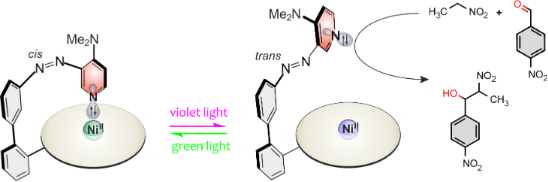
- of sugars [6], enzyme mimics [7], and the utilization of intermolecular cooperative effects [8] are further applications of photoswitchable catalysis. Particularly interesting and close to our approach is an early work by Inoue et al. who achieved control of the transformation of CO2 and 1,2

Graphical Abstract

Figure 1: Basicity and nucleophilicity switching of the 4-(N,N-dimethylamino)pyridine “record player” molecul...

Scheme 1: Synthesis of 4-N,N-dimethylamino record player molecule 1 by Suzuki reaction between Ni-porphyrin p...

Figure 2: Composition of the different states of porphyrin 1 (1 mM) in the PSS at 530 nm and 435 nm, determin...

Figure 3: a) UV–vis cuvette with a solution of porphyrin 1 (13.1 µM in THF) and the corresponding UV–vis spec...

Scheme 2: General scheme of the nitroaldol (Henry) reaction that was used to investigate photoswitchable cata...

Scheme 3: DMAP (2), azopyridine trans-4, record player trans- and cis-1 and Ni-porphyrin 8 were used in kinet...

Figure 4: Conversion of 4-nitrobenzaldehyde (6) in the Henry reaction with nitroethane (5) as a function of t...
Three new O-isocrotonyl-3-hydroxybutyric acid congeners produced by a sea anemone-derived marine bacterium of the genus Vibrio
- Dandan Li,
- Enjuro Harunari,
- Tao Zhou,
- Naoya Oku and
- Yasuhiro Igarashi
Beilstein J. Org. Chem. 2020, 16, 1869–1874, doi:10.3762/bjoc.16.154
- culture for 12 h at 37 °C in an atmosphere of 95% air and 5% CO2 saturated with H2O, the drug solutions were transferred into each cell culture to make up 200 μL of the culture. The highest concentration of the vehicle solvents (MeOH or DMSO) was set at 0.5 vol %, where the growth of the cells was not

Graphical Abstract

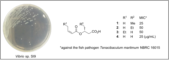
Figure 1: Structures of the compounds 1–5.

Figure 2: COSY (bold lines) and selected HMBC correlations (arrows) for 1–4.

Figure 3: a) Distribution of positive (red) and negative (blue) Δδ(S − R) values (in ppm) calculated from the ...
Polarity effects in 4-fluoro- and 4-(trifluoromethyl)prolines
- Vladimir Kubyshkin
Beilstein J. Org. Chem. 2020, 16, 1837–1852, doi:10.3762/bjoc.16.151
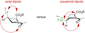
- this weakens their interaction. Similar considerations can be applied to the acidity of the carboxylic group (Figure 6B), where the mutual orientation of the C–X dipole and the carboxylate -CO2− charge has an effect [74]. In diastereomeric fluoroprolines there is a large difference in the mutual

Graphical Abstract

Figure 1: A) Three types of the backbone amino acid structures that are included in protein translation: glyc...

Figure 2: The set of amino acids examined in this study.

Figure 3: Design of the model system.

Figure 4: Propagation of the C4-conformation into the values of the J coupling in the C2H–C3H2 fragments.

Figure 5: Preferred side-chain conformations according to the multiplicity data.

Figure 6: A) The basicity reduction from the introduction of the dipoles reflects the preferred conformation ...

Figure 7: The lipophilicity data of the model compounds.

Figure 8: The expectations regarding the amide-bond rotation preferences in 1–4.

Figure 9: The explanation for the difference in the rotation barriers in the diastereomeric (A), 4-(trifluoro...

Figure 10: A) The structures of difluorinated model compounds 5 and 6, and the fluorine-free reference 7. B) B...
One-pot synthesis of oxazolidinones and five-membered cyclic carbonates from epoxides and chlorosulfonyl isocyanate: theoretical evidence for an asynchronous concerted pathway
- Esra Demir,
- Ozlem Sari,
- Yasin Çetinkaya,
- Ufuk Atmaca,
- Safiye Sağ Erdem and
- Murat Çelik
Beilstein J. Org. Chem. 2020, 16, 1805–1819, doi:10.3762/bjoc.16.148
- oxazolidinones and five-membered cyclic carbonates of various structures. The most well-known strategies for the synthesis of oxazolidinones are the reaction of an amino alcohol with phosgene [5][22], the carbonylation reaction of β-amino alcohols with CO2 or dialkyl carbonates [23][24][25][26][27], the
- multicomponent reaction of rare-earth metal amides [28], the reaction of CO2 with propargylamines or aziridines [29][30] and the cycloaddition reaction of epoxides with isocyanates [31][32]. On the other hand, for the synthesis of five-membered cyclic carbonates, the cycloaddition of CO2 to epoxides, the

Graphical Abstract

Scheme 1: Oxazolidinone (1), five-membered cyclic carbonate (2) and some important compounds containing an ox...

Scheme 2: Proposed mechanisms by Keshava Murthy and Dhar [41] and De Meijere and co-workers [42].

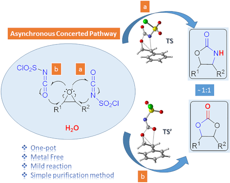
Figure 1: Possible pathways for the formation of oxazolidinone intermediates 10 and 11. Optimized transition ...

Figure 2: Potential energy profile related to the formation of oxazolidinone intermediates 10 and 11 at the P...

Figure 3: IRC calculated for the formation of (a) 10 and (b) 11 at M06-2X/6-31+G(d,p) level. I-1, I-15, I-35, ...

Figure 4: Optimized geometries for the stationary points for the formation of 10 at PCM(DCM)/M06-2X/6-31+G(d,...

Scheme 3: Proposed mechanisms for the formation of oxazolidinone 9f.

Figure 5: Potential energy profiles for paths 1a (blue), 1b (red), 2 (green) and relative Gibbs free energies...

Figure 6: Optimized geometries for the stationary points of path 1b at PCM(DCM)/M06-2X/6-31+G(d,p)//M06-2X/6-...

Scheme 4: Proposed mechanism for the formation of five-membered cyclic carbonate 8f.

Figure 7: Potential energy profile and relative Gibbs free energies (kcal/mol) in DCM related to the formatio...

Figure 8: Optimized geometries for the stationary points of step 1 for the formation of 16 at PCM(DCM)/M06-2X...

Figure 9: Optimized geometries for the stationary points of step 2 for the formation of 17 at PCM(DCM)/M06-2X...

Figure 10: Optimized geometries for the stationary points of step 3 for the formation of PC8 at PCM(DCM)/M06-2...
Pauson–Khand reaction of fluorinated compounds
- Jorge Escorihuela,
- Daniel M. Sedgwick,
- Alberto Llobat,
- Mercedes Medio-Simón,
- Pablo Barrio and
- Santos Fustero
Beilstein J. Org. Chem. 2020, 16, 1662–1682, doi:10.3762/bjoc.16.138

- , mild oxidizing additives such as amine oxides, aminophosphines, phosphine oxides, and sulfoxides may be used as promoters to facilitate the dissociation step, by oxidatively removing one of the CO ligands in form of CO2 [40]. The most common oxidants are N-morpholine N-oxide (NMO), trimethylamine N
- -workers [46]. In this study, a wide variety of 1,6-enynes bearing fluorine atoms or fluorine-containing groups at the alkenyl or alkynyl positions were synthesized and evaluated as substrates in the intramolecular PKR with dicobalt octacarbonyl [Co2(CO)8] in CH2Cl2 and promoted by NMO. In general, the
- to high yields, except for those bearing marked electron withdrawing groups (Scheme 7). In 2005, Billard and co-workers reported the PKR of α-trifluoromethylated homoallylamine derivatives (Scheme 8) [47]. Both 1,7-enynes 18a and 18b (n = 1) underwent PKR in the presence of 1 equiv of Co2(CO)8 and 10

Graphical Abstract

Scheme 1: Schematic representation of the Pauson–Khand reaction.

Scheme 2: Substrates included in this review.

Scheme 3: Commonly accepted mechanism for the Pauson–Khand reaction.

Scheme 4: Regioselectivity of the PKR.

Scheme 5: Variability at the acetylenic and olefinic counterpart.

Scheme 6: Pauson–Khand reaction of fluoroolefinic enynes reported by the group of Ishizaki [46].

Scheme 7: PKR of enynes bearing fluorinated groups on the alkynyl moiety, reported by the group of Ishizaki [46]....

Scheme 8: Intramolecular PKR of 1,7-enynes reported by the group of Billard [47].

Scheme 9: Intramolecular PKR of 1,7-enynes reported by the group of Billard [48].

Scheme 10: Intramolecular PKR of 1,7-enynes by the group of Bonnet-Delpon [49]. Reaction conditions: i) Co(CO)8 (1...

Scheme 11: Intramolecular PKR of 1,6-enynes reported by the group of Ichikawa [50].

Scheme 12: Intramolecular Rh(I)-catalyzed PKR reported by the group of Hammond [52].

Scheme 13: Intramolecular PKR of allenynes reported by the group of Osipov [53].

Scheme 14: Intramolecular PKR of 1,7-enynes reported by the group of Osipov [53].

Scheme 15: Intramolecular PKR of fluorine-containing 1,6-enynes reported by the Konno group [54].

Scheme 16: Diastereoselective PKR with enantioenriched fluorinated enynes 34 [55].

Scheme 17: Intramolecular PKR reported by the group of Martinez-Solorio [56].

Scheme 18: Fluorine substitution at the olefinic counterpart.

Scheme 19: Synthesis of fluorinated enynes 37 [59].

Scheme 20: Fluorine-containing substrates in PKR [59].
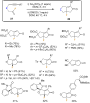
Scheme 21: Pauson Khand reaction for fluorinated enynes by the Fustero group: scope and limitations [59].

Scheme 22: Synthesis of chloro and bromo analogues [59].

Scheme 23: Dimerization pathway [59].

Scheme 24: Synthesis of fluorine-containing N-tethered 1,7-enynes [61].

Scheme 25: Intramolecular PKR of chiral N-tethered fluorinated 1,7-enynes [61].

Scheme 26: Examples of further modifications to the Pauson−Khand adducts [61].

Scheme 27: Asymmetric synthesis the fluorinated enynes 53.

Scheme 28: Intramolecular PKR of chiral N-tethered 1,7-enynes 53 [64].

Scheme 29: Intramolecular PKR of chiral N-tethered 1,7-enyne bearing a vinyl fluoride [64].

Scheme 30: Catalytic intramolecular PKR of chiral N-tethered 1,7-enynes [64].

Scheme 31: Model fluorinated alkynes used by Riera and Fustero [70].

Scheme 32: PKR with norbornadiene and fluorinated alkynes 58 [71].

Scheme 33: Nucleophilic addition/detrifluoromethylation and retro Diels-Alder reactions [70].

Scheme 34: Tentative mechanism for the nucleophilic addition/retro-aldol reaction sequence.

Scheme 35: Catalytic PKR with norbornadiene [70].

Scheme 36: Scope of the PKR of trifluoromethylalkynes with norbornadiene [72].

Scheme 37: DBU-mediated detrifluoromethylation [72].

Scheme 38: A simple route to enone 67, a common intermediate in the total synthesis of α-cuparenone.

Scheme 39: Effect of the olefin partner in the regioselectivity of the PKR with trifluoromethyl alkynes [79].

Scheme 40: Intermolecular PKR of trifluoromethylalkynes with 2-norbornene reported by the group of Konno [54].

Scheme 41: Intermolecular PKR of diarylalkynes with 2-norbornene reported by the group of Helaja [80].

Scheme 42: Intermolecular PKR reported by León and Fernández [81].

Scheme 43: PKR reported with cyclopropene 73 [82].
Heterogeneous photocatalysis in flow chemical reactors
- Christopher G. Thomson,
- Ai-Lan Lee and
- Filipe Vilela
Beilstein J. Org. Chem. 2020, 16, 1495–1549, doi:10.3762/bjoc.16.125
- synthetically controlled to improve the photocatalytic CO2 reduction performance by Zhang and co-workers using plasma treatment [87]. The general process of photocatalysis in metal oxide semiconductors is illustrated in Figure 4 and is as follows: the photoexcitation of an electron across the band gap generates

Graphical Abstract

Figure 1: A) Bar chart of the publications per year for the topics “Photocatalysis” (49,662 instances) and “P...

Figure 2: A) Professor Giacomo Ciamician and Dr. Paolo Silber on their roof laboratory at the University of B...

Scheme 1: PRC trifluoromethylation of N-methylpyrrole (1) using hazardous gaseous CF3I safely in a flow react...

Figure 3: A) Unit cells of the three most common crystal structures of TiO2: rutile, brookite, and anatase. R...

Figure 4: Illustration of the key semiconductor photocatalysis events: 1) A photon with a frequency exceeding...
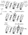
Figure 5: Photocatalytic splitting of water by oxygen vacancies on a TiO2(110) surface. Reprinted with permis...

Figure 6: Proposed adsorption modes of A) benzene, B) chlorobenzene, C) toluene, D) phenol, E) anisole, and F...

Figure 7: Structures of the sulfonate-containing organic dyes RB5 (3) and MX-5B (4) and the adsorption isothe...

Figure 8: Idealised triclinic unit cell of a g-C3N4 type polymer, displaying possible hopping transport scena...

Figure 9: Idealised structure of a perfect g-C3N4 sheet. The central unit highlighted in red represents one t...

Figure 10: Timeline of the key processes of charge transport following the photoexcitation of g-C3N4, leading ...

Scheme 2: Photocatalytic bifunctionalisation of heteroarenes using mpg-C3N4, with the selected examples 5 and ...

Figure 11: A) Structure of four linear conjugated polymer photocatalysts for hydrogen evolution, displaying th...

Figure 12: Graphical representation of the common methods used to immobilise molecular photocatalysts (PC) ont...

Figure 13: Wireless light emitter-supported TiO2 (TiO2@WLE) HPCat spheres powered by resonant inductive coupli...

Figure 14: Graphical representation of zinc–perylene diimide (Zn-PDI) supramolecular assembly photocatalysis v...

Scheme 3: Upconversion of NIR photons to the UV frequency by NaYF4:Yb,Tm nanocrystals sequentially coated wit...

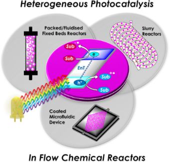
Figure 15: Types of reactors employed in heterogeneous photocatalysis in flow. A) Fixed bed reactors and the s...

Figure 16: Electrochemical potential of common semiconductor, transition metal, and organic dye-based photocat...

Scheme 4: Possible mechanisms of an immobilised molecular photoredox catalyst by oxidative or reductive quenc...
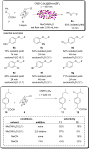
Scheme 5: Scheme of the CMB-C3N4 photocatalytic decarboxylative fluorination of aryloxyacetic acids, with the...

Scheme 6: Scheme of the g-C3N4 photocatalytic desilylative coupling reaction in flow and proposed mechanism [208].

Scheme 7: Proposed mechanism of the radical cyclisation of unsaturated alkyl 2-bromo-1,3-dicarbonyl compounds...

Scheme 8: N-alkylation of benzylamine and schematic of the TiO2-coated microfluidic device [213].

Scheme 9: Proposed mechanism of the Pt@TiO2 photocatalytic deaminitive cyclisation of ʟ-lysine (23) to ʟ-pipe...
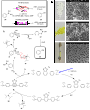
Scheme 10: A) Proposed mechanism for the photocatalytic oxidation of phenylboronic acid (24). B) Photos and SE...

Scheme 11: Proposed mechanism for the DA-CMP3 photocatalytic aza-Henry reaction performed in a continuous flow...

Scheme 12: Proposed mechanism for the formation of the cyclic product 32 by TiO2-NC HPCats in a slurry flow re...

Scheme 13: Reaction scheme for the photocatalytic synthesis of homo and hetero disulfides in flow and scope of...

Scheme 14: Reaction scheme for the MoOx/TiO2 HPCat oxidation of cyclohexane (34) to benzene. The graph shows t...

Scheme 15: Proposed mechanism of the TiO2 HPC heteroarene C–H functionalisation via aryl radicals generated fr...

Scheme 16: Scheme of the oxidative coupling of benzylamines with the HOTT-HATN HPCat and selected examples of ...
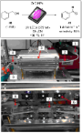
Scheme 17: Photocatalysis oxidation of benzyl alcohol (40) to benzaldehyde (41) in a microflow reactor coated ...

Figure 17: Mechanisms of Dexter and Forster energy transfer.
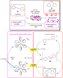
Scheme 18: Continuous flow process for the isomerisation of alkenes with an ionic liquid-immobilised photocata...

Scheme 19: Singlet oxygen synthetic step in the total synthesis of canataxpropellane [265].
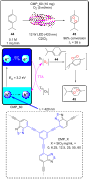
Scheme 20: Scheme and proposed mechanism of the singlet oxygen photosensitisation by CMP_X HPCats, with the st...

Scheme 21: Structures of CMP HPCat materials applied by Vilela and co-workers for the singlet oxygen photosens...
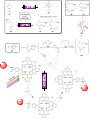
Scheme 22: Polyvinylchloride resin-supported TDCPP photosensitisers applied for singlet oxygen photosensitisat...

Scheme 23: Structure of the ionically immobilised TPP photosensitiser on amberlyst-15 ion exchange resins (TPP...

Scheme 24: Photosensitised singlet oxygen oxidation of citronellol (46) in scCO2, with automatic phase separat...

Scheme 25: Schematic of PS-Est-BDP-Cl2 being applied for singlet oxygen photosensitisation in flow. A) Pseudo-...

Scheme 26: Reaction scheme of the singlet oxygen oxidation of furoic acid (54) using a 3D-printed microfluidic...

Figure 18: A) Photocatalytic bactericidal mechanism by ROS oxidative cleavage of membrane lipids (R = H, amino...

Figure 19: A) Suggested mechanisms for the aqueous pollutant degradation by TiO2 in a slurry flow reactor [284-287]. B)...

Figure 20: Schematic of the flow system used for the degradation of aqueous oxytetracycline (56) solutions [215]. M...
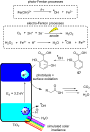
Scheme 27: Degradation of a salicylic acid (57) solution by a coupled solar photoelectro-Fenton (SPEF) process...

Figure 21: A) Schematic flow diagram using the TiO2-coated NETmix microfluidic device for an efficient mass tr...
Activated carbon as catalyst support: precursors, preparation, modification and characterization
- Melanie Iwanow,
- Tobias Gärtner,
- Volker Sieber and
- Burkhard König
Beilstein J. Org. Chem. 2020, 16, 1188–1202, doi:10.3762/bjoc.16.104
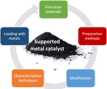
- methods from coal precursors. Yang et al. synthesized nitrogen-doped activated carbon from petroleum coke for an enhanced CO2 capture [7]. Pietrzak et al. used high volatile bituminous coals, brown coals and anthracites for modified activated carbon preparation [5][10][11][12]. Lillo-Ródenas et al
- solutions Xu et al. used energy-rich carbon precursors for the spherical carbon preparation via ultrasonic spray pyrolysis. Lithium, sodium or potassium propiolates are one class of such energy rich materials and exhibit leaving groups such as CO, CO2 or C2H2 eliminated by decarbonylation or decarboxylation
- . After preparation of char by carbonization of the precursor materials for a certain time at a defined temperature under inert gas atmosphere, steam, air or CO2 activate the materials at higher temperatures (800–1000 °C) to form a porous structure according to the Equations 1–3 [81][85][86]. It is

Graphical Abstract

Figure 1: Experimental setup of ultrasonic spray pyrolysis. Reprinted with permission from [95], copyright 2006 T...

Figure 2: Overview of nitrogen-containing functional groups on the surface of activated carbons. Scheme was d...
Photocatalysis with organic dyes: facile access to reactive intermediates for synthesis
- Stephanie G. E. Amos,
- Marion Garreau,
- Luca Buzzetti and
- Jerome Waser
Beilstein J. Org. Chem. 2020, 16, 1163–1187, doi:10.3762/bjoc.16.103
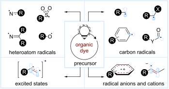
- difficult to be directly activated by the excited state photocatalyst. For these reasons, the photocatalyzed decarboxylation often proceeds on the corresponding carboxylates, which are easier to be oxidized. This photoinduced SET, followed by the loss of CO2 as the sole byproduct, gives access to the
- reducible moiety, such as a redox-active ester (RAE). These species can accept one electron from the photocatalyst, and the ensuing reduced species releases the corresponding C(sp3) radical after a fragmentation and CO2 loss. This approach represents an alternative to oxidative decarboxylations, allowing

Graphical Abstract
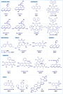
Figure 1: Selected examples of organic dyes. Mes-Acr+: 9-mesityl-10-methylacridinium, DCA: 9,10-dicyanoanthra...

Scheme 1: Activation modes in photocatalysis.

Scheme 2: Main strategies for the formation of C(sp3) radicals used in organophotocatalysis.

Scheme 3: Illustrative example for the photocatalytic oxidative generation of radicals from carboxylic acids:...

Scheme 4: Illustrative example for the photocatalytic reductive generation of C(sp3) radicals from redoxactiv...

Figure 2: Common substrates for the photocatalytic oxidative generation of C(sp3) radicals.
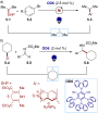
Scheme 5: Illustrative example for the photocatalytic oxidative generation of radicals from dihydropyridines ...

Scheme 6: Illustrative example for the photocatalytic oxidative generation of C(sp3) radicals from trifluorob...

Scheme 7: Illustrative example for the photocatalytic reductive generation of C(sp3) radicals from benzylic h...

Scheme 8: Illustrative example for the photocatalytic generation of C(sp3) radicals via direct HAT: the cross...

Scheme 9: Illustrative example for the photocatalytic generation of C(sp3) radicals via indirect HAT: the deu...

Scheme 10: Selected precursors for the generation of aryl radicals using organophotocatalysis.

Scheme 11: Illustrative example for the photocatalytic reductive generation of aryl radicals from aryl diazoni...

Scheme 12: Illustrative examples for the photocatalytic reductive generation of aryl radicals from haloarenes:...

Scheme 13: Illustrative example for the photocatalytic reductive generation of aryl radicals from aryl halides...

Scheme 14: Illustrative example for the photocatalytic reductive generation of aryl radicals from arylsulfonyl...

Scheme 15: Illustrative example for the reductive photocatalytic generation of aryl radicals from triaryl sulf...

Scheme 16: Main strategies towards acyl radicals used in organophotocatalysis.

Scheme 17: Illustrative example for the decarboxylative photocatalytic generation of acyl radicals from α-keto...

Scheme 18: Illustrative example for the oxidative photocatalytic generation of acyl radicals from acyl silanes...

Scheme 19: Illustrative example for the oxidative photocatalytic generation of carbamoyl radicals from 4-carba...

Scheme 20: Illustrative example of the photocatalytic HAT approach for the generation of acyl radicals from al...

Scheme 21: General reactivity of a) radical cations; b) radical anions; c) the main strategies towards aryl an...

Scheme 22: Illustrative example for the oxidative photocatalytic generation of alkene radical cations from alk...

Scheme 23: Illustrative example for the reductive photocatalytic generation of an alkene radical anion from al...

Figure 3: Structure of C–X radical anions and their neutral derivatives.

Scheme 24: Illustrative example for the photocatalytic reduction of imines and the generation of an α-amino C(...

Scheme 25: Illustrative example for the oxidative photocatalytic generation of aryl radical cations from arene...

Scheme 26: NCR classifications and generation.

Scheme 27: Illustrative example for the photocatalytic reductive generation of iminyl radicals from O-aryl oxi...

Scheme 28: Illustrative example for the photocatalytic oxidative generation of iminyl radicals from α-N-oxy ac...

Scheme 29: Illustrative example for the photocatalytic oxidative generation of iminyl radicals via an N–H bond...

Scheme 30: Illustrative example for the photocatalytic oxidative generation of amidyl radicals from Weinreb am...

Scheme 31: Illustrative example for the photocatalytic reductive generation of amidyl radicals from hydroxylam...

Scheme 32: Illustrative example for the photocatalytic reductive generation of amidyl radicals from N-aminopyr...

Scheme 33: Illustrative example for the photocatalytic oxidative generation of amidyl radicals from α-amido-ox...

Scheme 34: Illustrative example for the photocatalytic oxidative generation of aminium radicals: the N-aryltet...

Scheme 35: Illustrative example for the photocatalytic oxidative generation of nitrogen-centered radical catio...

Scheme 36: Illustrative example for the photocatalytic oxidative generation of nitrogen-centered radical catio...

Scheme 37: Illustrative example for the photocatalytic oxidative generation of hydrazonyl radical from hydrazo...

Scheme 38: Generation of O-radicals.

Scheme 39: Illustrative examples for the photocatalytic generation of O-radicals from N-alkoxypyridinium salts...

Scheme 40: Illustrative examples for the photocatalytic generation of O-radicals from alkyl hydroperoxides: th...

Scheme 41: Illustrative example for the oxidative photocatalytic generation of thiyl radicals from thiols: the...

Scheme 42: Main strategies and reagents for the generation of sulfonyl radicals used in organophotocatalysis.

Scheme 43: Illustrative example for the reductive photocatalytic generation of sulfonyl radicals from arylsulf...

Scheme 44: Illustrative example of a Cl atom abstraction strategy for the photocatalytic generation of sulfamo...

Scheme 45: Illustrative example for the oxidative photocatalytic generation of sulfonyl radicals from sulfinic...

Scheme 46: Illustrative example for the photocatalytic generation of electronically excited triplet states: th...

Scheme 47: Illustrative example for the photocatalytic generation of electronically excited triplet states: th...
Recent applications of porphyrins as photocatalysts in organic synthesis: batch and continuous flow approaches
- Rodrigo Costa e Silva,
- Luely Oliveira da Silva,
- Aloisio de Andrade Bartolomeu,
- Timothy John Brocksom and
- Kleber Thiago de Oliveira
Beilstein J. Org. Chem. 2020, 16, 917–955, doi:10.3762/bjoc.16.83
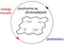
- also can be applied to the reduction of carbon dioxide (CO2). Many photocatalytic materials containing porphyrins have been developed for CO2 reactions in organic synthesis, including photoinduced transformations [52][53][54][55]. Nagaraja and co-workers reported the first porphyrin-based MOF for
- different epoxides, whose conversion was proportional to the substrate size, using MOF1 and tetra-n-butylammonium bromide (TBAB) as photocatalyst and co-catalyst, respectively (Scheme 25). A successful gram-scale protocol was developed opening up perspectives for using these materials in CO2 reuse
- . This work is crucial for the success of the subsequent industrial process introduced by the pharmaceutical company Sanofi [80]. After this seminal publication, a consortium between Sanofi and UK/China universities also reported a green protocol for artemisinin synthesis using supercritical CO2 as a

Graphical Abstract

Figure 1: Chemical structures of the porphyrinoids and their absorption spectra: in bold are highlighted the ...

Figure 2: Photophysical and photochemical processes (Por = porphyrin). Adapted from [12,18].

Figure 3: Main dual photocatalysts and their oxidative/reductive excited state potentials, including porphyri...

Scheme 1: Photoredox alkylation of aldehydes with diazo acetates using porphyrins and a Ru complex. aUsing a ...

Scheme 2: Proposed mechanism for the alkylation of aldehydes with diazo acetates in the presence of TPP.
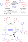
Scheme 3: Arylation of heteroarenes with aryldiazonium salts using TPFPP as photocatalyst, and corresponding ...

Scheme 4: A) Scope with different aryldiazonium salts and enol acetates. B) Photocatalytic cycles and compari...

Scheme 5: Photoarylation of isopropenyl acetate A) Comparison between batch and continuous-flow approaches an...

Scheme 6: Dehalogenation induced by red light using thiaporphyrin (STPP).

Scheme 7: Applications of NiTPP as both photoreductant and photooxidant.

Scheme 8: Proposed mechanism for obtaining tetrahydroquinolines by reductive quenching.

Scheme 9: Selenylation and thiolation of anilines.

Scheme 10: NiTPP as photoredox catalyst in oxidative and reductive quenching, in comparison with other photoca...

Scheme 11: C–O bond cleavage of 1-phenylethanol using a cobalt porphyrin (CoTMPP) under visible light.

Scheme 12: Hydration of terminal alkynes by RhIII(TSPP) under visible light irradiation.

Scheme 13: Regioselective photocatalytic hydro-defluorination of perfluoroarenes by RhIII(TSPP).

Scheme 14: Formation of 2-methyl-2,3-dihydrobenzofuran by intramolecular hydro-functionalization of allylpheno...
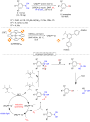
Scheme 15: Photocatalytic oxidative hydroxylation of arylboronic acids using UNLPF-12 as heterogeneous photoca...

Scheme 16: Photocatalytic oxidative hydroxylation of arylboronic acids using MOF-525 as heterogeneous photocat...

Scheme 17: Preparation of the heterogeneous photocatalyst CNH.

Scheme 18: Photoinduced sulfonation of alkenes with sulfinic acid using CNH as photocatalyst.

Scheme 19: Sulfonic acid scope of the sulfonation reactions.

Scheme 20: Regioselective sulfonation reaction of arimistane.

Scheme 21: Synthesis of quinazolin-4-(3H)-ones.

Scheme 22: Selective photooxidation of aromatic benzyl alcohols to benzaldehydes using Pt/PCN-224(Zn).

Scheme 23: Photooxidation of benzaldehydes to benzoic acids using Pt or Pd porphyrins.

Scheme 24: Photocatalytic reduction of various nitroaromatics using a Ni-MOF.

Scheme 25: Photoinduced cycloadditions of CO2 with epoxides by MOF1.

Figure 4: Electronic configurations of the species of oxygen. Adapted from [66].

Scheme 26: TPP-photocatalyzed generation of 1O2 and its application in organic synthesis. Adapted from [67-69].

Scheme 27: Pericyclic reactions involving singlet oxygen and their mechanisms. Adapted from [67].

Scheme 28: First scaled up ascaridole preparation from α-terpinene.

Scheme 29: Antimalarial drug synthesis using an endoperoxidation approach.

Scheme 30: Photooxygenation of colchicine.

Scheme 31: Synthesis of (−)-pinocarvone from abundant (+)-α-pinene.

Scheme 32: Seeberger’s semi-synthesis of artemisinin.

Scheme 33: Synthesis of artemisinin using TPP and supercritical CO2.

Scheme 34: Synthesis of artemisinin using chlorophyll a.

Scheme 35: Quercitol stereoisomer preparation.

Scheme 36: Photocatalyzed preparation of naphthoquinones.

Scheme 37: Continuous endoperoxidation of conjugated dienes and subsequent rearrangements leading to oxidized ...

Scheme 38: The Opatz group total synthesis of (–)-oxycodone.

Scheme 39: Biomimetic syntheses of rhodonoids A, B, E, and F.

Scheme 40: α-Photooxygenation of chiral aldehydes.

Scheme 41: Asymmetric photooxidation of indanone β-keto esters by singlet oxygen using PTC as a chiral inducer...

Scheme 42: Asymmetric photooxidation of both β-keto esters and β-keto amides by singlet oxygen using PTC-2 as ...

Scheme 43: Bifunctional photo-organocatalyst used for the asymmetric oxidation of β-keto esters and β-keto ami...

Scheme 44: Mechanism of singlet oxygen oxidation of sulfides to sulfoxides.

Scheme 45: Controlled oxidation of sulfides to sulfoxides using protonated porphyrins as photocatalysts. aIsol...

Scheme 46: Photochemical oxidation of sulfides to sulfoxides using PdTPFPP as photocatalyst.

Scheme 47: Controlled oxidation of sulfides to sulfoxides using SnPor@PAF as a photosensitizer.

Scheme 48: Syntheses of 2D-PdPor-COF and 3D-Pd-COF.

Scheme 49: Photocatalytic oxidation of A) thioanisole to methyl phenyl sulfoxide and B) various aryl sulfides,...

Scheme 50: General mechanism for oxidation of amines to imines.

Scheme 51: Oxidation of secondary amines to imines.

Scheme 52: Oxidation of secondary amines using Pd-TPFPP as photocatalyst.

Scheme 53: Oxidative amine coupling using UNLPF-12 as heterogeneous photocatalyst.

Scheme 54: Synthesis of Por-COF-1 and Por-COF-2.

Scheme 55: Photocatalytic oxidation of amines to imines by Por-COF-2.

Scheme 56: Photocyanation of primary amines.

Scheme 57: Synthesis of ᴅ,ʟ-tert-leucine hydrochloride.

Scheme 58: Photocyanation of catharanthine and 16-O-acetylvindoline using TPP.

Scheme 59: Photochemical α-functionalization of N-aryltetrahydroisoquinolines using Pd-TPFPP as photocatalyst.

Scheme 60: Ugi-type reaction with 1,2,3,4-tetrahydroisoquinoline using molecular oxygen and TPP.

Scheme 61: Ugi-type reaction with dibenzylamines using molecular oxygen and TPP.

Scheme 62: Mannich-type reaction of tertiary amines using PdTPFPP as photocatalyst.

Scheme 63: Oxidative Mannich reaction using UNLPF-12 as heterogeneous photocatalyst.

Scheme 64: Transformation of amines to α-cyanoepoxides and the proposed mechanism.
Cation-induced ring-opening and oxidation reaction of photoreluctant spirooxazine–quinolizinium conjugates
- Phil M. Pithan,
- Sören Steup and
- Heiko Ihmels
Beilstein J. Org. Chem. 2020, 16, 904–916, doi:10.3762/bjoc.16.82
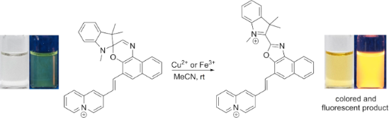
- , within the series of representative alkali and earth alkali ions (Li+, Na+, K+, Mg2+, Ca2+) and transition metal cations (Mn2+, Fe2+, Co2+, Ni2+, Cu2+, Zn2+, Ag+, Hg2+, Pb2+), only the addition of Cu2+ caused a significant coloration of the initially colorless solution of 3a (c = 20 µM) in MeCN (Figure 1
- . Absorption (A) and fluorescence spectrum (B) of 3a in MeCN (c = 5 µM) in the absence (black) and in the presence of metal ions ca. 1 h after the addition. Red: Cu2+ (c = 15 µM), orange: Hg2+ (c = 100 µM), blue: Li+, Na+, K+, Mg2+, Ca2+, Mn2+, Fe2+, Co2+, Ni2+, Zn2+, Ag+, and Pb2+ (c = 100 µM each); λex = 470

Graphical Abstract

Scheme 1: Photo- or cation-induced ring-opening reaction of spirooxazine 1aSO; Mn+ = Pb2+, La3+, Eu3+, Tb3+ [17].

Scheme 2: Synthesis of the spirooxazine–quinolizinium conjugates 3a and 3b.

Figure 1: Colors of the solutions resulting from the addition of metal ions (c = 50 µM) to derivative 3a (c =...

Figure 2: Spectrophotometric titration of 3a (A) and 3b (B) (c = 20 µM) with Cu(BF4)2 (c = 2.44 mM) in MeCN. ...

Figure 3: Absorption (A) and fluorescence spectrum (B) of 3a in MeCN (c = 5 µM) in the absence (black) and in...

Figure 4: Emission colors of solutions resulting from the addition of metal ions (c = 50 µM) to derivative 3a...

Scheme 3: Cu2+-induced formation of the oxazole derivatives 4a and 4b.

Figure 5: 1H NMR spectra (600 MHz, 6.4–9.4 ppm) of 3a (c = 2.0 mM) in the absence (A) and in the presence (B–...

Figure 6: Spectral changes of 3a (c = 20 µM) upon the addition of Cu2+ (A) and Fe3+ (B) (cM+ = 60 µM) in MeCN...

Scheme 4: Proposed mechanism for the formation of the oxazole derivatives 4a and 4b (cf. Scheme 3); Mn+ = Cu2+, Fe3+,...
Recent advances in Cu-catalyzed C(sp3)–Si and C(sp3)–B bond formation
- Balaram S. Takale,
- Ruchita R. Thakore,
- Elham Etemadi-Davan and
- Bruce H. Lipshutz
Beilstein J. Org. Chem. 2020, 16, 691–737, doi:10.3762/bjoc.16.67
- give excellent chemical yields with good enantioselectivities for products 57–59 (Scheme 14). Interestingly, this approach could be extended to the synthesis of amino acids using cesium fluoride in the presence of CO2 gas to afford 60 and 61. From the representative examples shown below, it appears
- developed by Suginome [125], or B2pin2, along with various N-hydroxylamine derivatives (400) under ligand-influenced Cu catalysis, high regioselectivities were typically obtained [126]. A year later, Popp et al. reported a Cu-catalyzed regiospecific boracarboxylation of vinyl arenes using 1 atm CO2 and

Graphical Abstract

Scheme 1: Pharmaceuticals possessing a silicon or boron atom.

Scheme 2: The first Cu-catalyzed C(sp3)–Si bond formation.

Scheme 3: Conversion of benzylic phosphate 6 to the corresponding silane.

Scheme 4: Conversion of alkyl triflates to alkylsilanes.

Scheme 5: Conversion of secondary alkyl triflates to alkylsilanes.

Scheme 6: Conversion of alkyl iodides to alkylsilanes.

Scheme 7: Trapping of intermediate radical through cascade reaction.

Scheme 8: Radical pathway for conversion of alkyl iodides to alkylsilanes.

Scheme 9: Conversion of alkyl ester of N-hydroxyphthalimide to alkylsilanes.

Scheme 10: Conversion of gem-dibromides to bis-silylalkanes.

Scheme 11: Conversion of imines to α-silylated amines (A) and the reaction pathway (B).

Scheme 12: Conversion of N-tosylimines to α-silylated amines.

Scheme 13: Screening of diamine ligands.

Scheme 14: Conversion of N-tert-butylsulfonylimines to α-silylated amines.

Scheme 15: Conversion of aldimines to nonracemic α-silylated amines.

Scheme 16: Conversion of N-tosylimines to α-silylated amines.

Scheme 17: Reaction pathway [A] and conversion of aldehydes to α-silylated alcohols [B].

Scheme 18: Conversion of aldehydes to benzhydryl silyl ethers.

Scheme 19: Conversion of ketones to 1,2-diols (A) and conversion of imines to 1,2-amino alcohols (B).

Scheme 20: Ligand screening (A) and conversion of aldehydes to α-silylated alcohols (B).

Scheme 21: Conversion of aldehydes to α-silylated alcohols.

Scheme 22: 1,4-Additions to α,β-unsaturated ketones.

Scheme 23: 1,4-Additions to unsaturated ketones to give β-silylated derivatives.

Scheme 24: Additions onto α,β-unsaturated lactones to give β-silylated lactones.

Scheme 25: Conversion of α,β-unsaturated to β-silylated lactams.

Scheme 26: Conversion of N-arylacrylamides to silylated oxindoles.

Scheme 27: Conversion of α,β-unsaturated carbonyl compounds to silylated tert-butylperoxides.

Scheme 28: Catalytic cycle for Cu(I) catalyzed α,β-unsaturated compounds.

Scheme 29: Conversion of p-quinone methides to benzylic silanes.

Scheme 30: Conversion of α,β-unsaturated ketimines to regio- and stereocontrolled allylic silanes.

Scheme 31: Conversion of α,β-unsaturated ketimines to enantioenriched allylic silanes.

Scheme 32: Regioselective conversion of dienedioates to allylic silanes.

Scheme 33: Conversion of alkenyl-substituted azaarenes to β-silylated adducts.

Scheme 34: Conversion of conjugated benzoxazoles to enantioenriched β-silylated adducts.

Scheme 35: Conversion of α,β-unsaturated carbonyl indoles to α-silylated N-alkylated indoles.

Scheme 36: Conversion of β-amidoacrylates to α-aminosilanes.

Scheme 37: Conversion of α,β-unsaturated ketones to enantioenriched β-silylated ketones, nitriles, and nitro d...

Scheme 38: Regio-divergent silacarboxylation of allenes.

Scheme 39: Silylation of diazocarbonyl compounds, (A) asymmetric and (B) racemic.

Scheme 40: Enantioselective hydrosilylation of alkenes.

Scheme 41: Conversion of 3-acylindoles to indolino-silanes.

Scheme 42: Proposed mechanism for the silylation of 3-acylindoles.

Scheme 43: Silyation of N-chlorosulfonamides.

Scheme 44: Conversion of acyl silanes to α-silyl alcohols.

Scheme 45: Conversion of N-tosylaziridines to β-silylated N-tosylamines.

Scheme 46: Conversion of N-tosylaziridines to silylated N-tosylamines.

Scheme 47: Conversion of 3,3-disubstituted cyclopropenes to silylated cyclopropanes.

Scheme 48: Conversion of conjugated enynes to 1,3-bis(silyl)propenes.

Scheme 49: Proposed sequence for the Cu-catalyzed borylation of substituted alkenes.

Scheme 50: Cu-catalyzed synthesis of nonracemic allylic boronates.

Scheme 51: Cu–NHC catalyzed synthesis of α-substituted allylboronates.
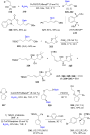
Scheme 52: Synthesis of α-chiral (γ-alkoxyallyl)boronates.

Scheme 53: Cu-mediated formation of nonracemic cis- or trans- 2-substituted cyclopropylboronates.

Scheme 54: Cu-catalyzed synthesis of γ,γ-gem-difluoroallylboronates.

Scheme 55: Cu-catalyzed hydrofunctionalization of internal alkenes and vinylarenes.

Scheme 56: Cu-catalyzed Markovnikov and anti-Markovnikov borylation of alkenes.

Scheme 57: Cu-catalyzed borylation/ortho-cyanation/Cope rearrangement.
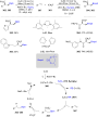
Scheme 58: Borylfluoromethylation of alkenes.

Scheme 59: Cu-catalyzed synthesis of tertiary nonracemic alcohols.

Scheme 60: Synthesis of densely functionalized and synthetically versatile 1,2- or 4,3-borocyanated 1,3-butadi...

Scheme 61: Cu-catalyzed trifunctionalization of allenes.

Scheme 62: Cu-catalyzed selective arylborylation of arenes.

Scheme 63: Asymmetric borylative coupling between styrenes and imines.

Scheme 64: Regio-divergent aminoboration of unactivated terminal alkenes.

Scheme 65: Cu-catalyzed 1,4-borylation of α,β-unsaturated ketones.

Scheme 66: Cu-catalyzed protodeboronation of α,β-unsaturated ketones.

Scheme 67: Cu-catalyzed β-borylation of α,β-unsaturated imines.

Scheme 68: Cu-catalyzed synthesis of β-trifluoroborato carbonyl compounds.

Scheme 69: Asymmetric 1,4-borylation of α,β-unsaturated carbonyl compounds.

Scheme 70: Cu-catalyzed ACB and ACA reactions of α,β-unsaturated 2-acyl-N-methylimidazoles.

Scheme 71: Cu-catalyzed diborylation of aldehydes.

Scheme 72: Umpolung pathway for chiral, nonracemic tertiary alcohol synthesis (top) and proposed mechanism for...

Scheme 73: Cu-catalyzed synthesis of α-hydroxyboronates.

Scheme 74: Cu-catalyzed borylation of ketones.

Scheme 75: Cu-catalyzed borylation of unactivated alkyl halides.

Scheme 76: Cu-catalyzed borylation of allylic difluorides.

Scheme 77: Cu-catalyzed borylation of cyclic and acyclic alkyl halides.

Scheme 78: Cu-catalyzed borylation of unactivated alkyl chlorides and bromides.

Scheme 79: Cu-catalyzed decarboxylative borylation of carboxylic acids.
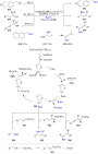
Scheme 80: Cu-catalyzed borylation of benzylic, allylic, and propargylic alcohols.
KOt-Bu-promoted selective ring-opening N-alkylation of 2-oxazolines to access 2-aminoethyl acetates and N-substituted thiazolidinones
- Qiao Lin,
- Shiling Zhang and
- Bin Li
Beilstein J. Org. Chem. 2020, 16, 492–501, doi:10.3762/bjoc.16.44
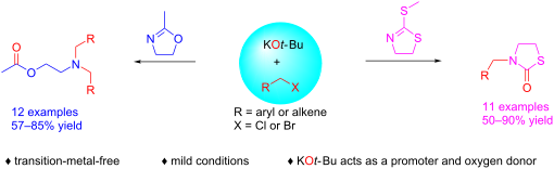
- TMSN3 as the azide source [10] (Scheme 1a). Coates described a Co2(CO)8-catalyzed ring-opening hydroformylation of oxazolines for the synthesis of β-amidoaldehydes [11] (Scheme 1a). However, the ring-opening N-alkylation of 2-oxazolines to produce 2-aminoethyl acetate derivatives under basic conditions

Graphical Abstract

Scheme 1: Comparison of different ring-opening reactions of 2-oxazolines and thiazolidinones synthesis.

Scheme 2: KOt-Bu-promoted selective ring-opening N-alkylation of 2-methyl-2-oxazoline with benzyl bromides. C...

Scheme 3: KOt-Bu-promoted selective ring-opening N-alkylation of 2-methyl-2-oxazoline with benzyl chlorides. ...

Scheme 4: KOt-Bu-promoted selective ring-opening N-alkylation of 2,4,4-trimethyl-4,5-dihydrooxazole (2b) with...

Scheme 5: KOt-Bu/I2-promoted selective N-alkylation to synthesis of thiazolidone derivatives. Conditions: KOt...

Scheme 6: Transformation of 2-aminoethyl acetate derivative to 2-(dibenzylamino)ethanol.

Scheme 7: Control experiments and 18O-labeling experiment.

Scheme 8: Control experiments with radical scavengers.

Scheme 9: Proposed mechanism.
Recent advances in photocatalyzed reactions using well-defined copper(I) complexes
- Mingbing Zhong,
- Xavier Pannecoucke,
- Philippe Jubault and
- Thomas Poisson
Beilstein J. Org. Chem. 2020, 16, 451–481, doi:10.3762/bjoc.16.42
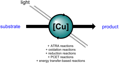
- reaction conditions. The authors suggested first the photoexcitation of a [Cu(I)] species. Then, the excited [Cu(I)]* species reduces the NHP ester to form a carboxyl radical and the phthalimide anion, which binds to the [Cu(II)] species. After the elimination of CO2, the recombination of the alkyl radical

Graphical Abstract

Scheme 1: [Cu(I)(dap)2]Cl-catalyzed ATRA reaction under green light irradiation.

Scheme 2: Photocatalytic allylation of α-haloketones.

Scheme 3: [Cu(I)(dap)2]Cl-photocatalyzed chlorosulfonylation and chlorotrifluoromethylation of alkenes.

Scheme 4: Photocatalytic perfluoroalkylchlorination of electron-deficient alkenes using the Sauvage catalyst.

Scheme 5: Photocatalytic synthesis of fluorinated sultones.
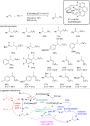
Scheme 6: Photocatalyzed haloperfluoroalkylation of alkenes and alkynes.
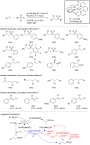
Scheme 7: Chlorosulfonylation of alkenes catalyzed by [Cu(I)(dap)2]Cl. aNo Na2CO3 was added. b1 equiv of Na2CO...

Scheme 8: Copper-photocatalyzed reductive allylation of diaryliodonium salts.

Scheme 9: Copper-photocatalyzed azidomethoxylation of olefins.

Scheme 10: Benzylic azidation initiated by [Cu(I)(dap)2]Cl.

Scheme 11: Trifluoromethyl methoxylation of styryl derivatives using [Cu(I)(dap)2]PF6. All redox potentials ar...

Scheme 12: Trifluoromethylation of silyl enol ethers.
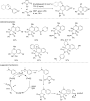
Scheme 13: Synthesis of annulated heterocycles upon oxidation with the Sauvage catalyst.
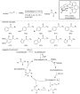
Scheme 14: Oxoazidation of styrene derivatives using [Cu(dap)2]Cl as a precatalyst.

Scheme 15: [Cu(I)(dpp)(binc)]PF6-catalyzed ATRA reaction.

Scheme 16: Allylation reaction of α-bromomalonate catalyzed by [Cu(I)(dpp)(binc)]PF6 following an ATRA mechani...

Scheme 17: Bromo/tribromomethylation reaction using [Cu(I)(dmp)(BINAP)]PF6.

Scheme 18: Chlorotrifluoromethylation of alkenes catalyzed by [Cu(I)(N^N)(xantphos)]PF6.

Scheme 19: Chlorosulfonylation of styrene and alkyne derivatives by ATRA reactions.

Scheme 20: Reduction of aryl and alkyl halides with the complex [Cu(I)(bcp)(DPEPhos)]PF6. aIrradiation was car...
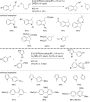
Scheme 21: Meerwein arylation of electron-rich aromatic derivatives and 5-exo-trig cyclization catalyzed by th...

Scheme 22: [Cu(I)(bcp)(DPEPhos)]PF6-photocatalyzed synthesis of alkaloids. aYield over two steps (cyclization ...

Scheme 23: Copper-photocatalyzed decarboxylative amination of NHP esters.

Scheme 24: Photocatalytic decarboxylative alkynylation using [Cu(I)(dq)(binap)]BF4.
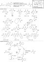
Scheme 25: Copper-photocatalyzed alkylation of glycine esters.

Scheme 26: Copper-photocatalyzed borylation of organic halides. aUnder continuous flow conditions.

Scheme 27: Copper-photocatalyzed α-functionalization of alcohols with glycine ester derivatives.
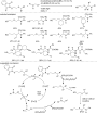
Scheme 28: δ-Functionalization of alcohols using [Cu(I)(dmp)(xantphos)]BF4.

Scheme 29: Photocatalytic synthesis of [5]helicene and phenanthrene.

Scheme 30: Oxidative carbazole synthesis using in situ-formed [Cu(I)(dmp)(xantphos)]BF4.
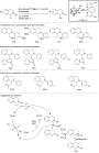
Scheme 31: Copper-photocatalyzed functionalization of N-aryl tetrahydroisoquinolines.

Scheme 32: Bicyclic lactone synthesis using a copper-photocatalyzed PCET reaction.

Scheme 33: Photocatalytic Pinacol coupling reaction catalyzed by [Cu(I)(pypzs)(BINAP)]BF4. The ligands of the ...

Scheme 34: Azide photosensitization using a Cu-based photocatalyst.
Two antibacterial and PPARα/γ-agonistic unsaturated keto fatty acids from a coral-associated actinomycete of the genus Micrococcus
- Amit Raj Sharma,
- Enjuro Harunari,
- Naoya Oku,
- Nobuyasu Matsuura,
- Agus Trianto and
- Yasuhiro Igarashi
Beilstein J. Org. Chem. 2020, 16, 297–304, doi:10.3762/bjoc.16.29
- the cells at a final density of 5 × 10³ cells/well, and 200 µL cultures thus made were incubated for 96 h at 37 °C in an atmosphere of 5% CO2 in air with 100% humidity. The viability of the cells was visualized by the addition of 50 μL of the medium containing XTT (1 mg/mL) and PMS (40 µg/mL) to each
- , and the plates were cultured for an additional 24 h at 37 °C in a 5% CO2 incubator. The luciferase activity and secreted alkaline phosphatase SEAP activity were measured in each well by using a Steady-Glo® luciferase assay (Promega, Madison, WI, USA) and Great ESCAPe SEAP Reporter System3 (Clontech

Graphical Abstract

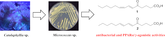
Figure 1: Structures of (6E,8Z)- and (6E,8E)-5-oxo-6,8-tetradecadienoic acids (1 and 2).

Figure 2: COSY and key HMBC correlations for 1 and 2.

Figure 3: Spin system simulation for the C8–C9 double bond of 2.

Figure 4: Natural keto fatty acids of various origins.
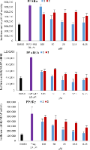
Figure 5: PPAR activation by 1 and 2.
Combination of multicomponent KA2 and Pauson–Khand reactions: short synthesis of spirocyclic pyrrolocyclopentenones
- Riccardo Innocenti,
- Elena Lenci,
- Gloria Menchi and
- Andrea Trabocchi
Beilstein J. Org. Chem. 2020, 16, 200–211, doi:10.3762/bjoc.16.23
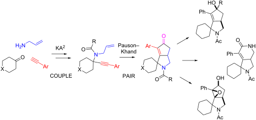
- slightly lower yield. Attempts to carry out the Pauson–Khand reaction directly on the amino group before the acylation step did not work, nor using a modified approach using ammonium chloride and 1.5 equivalents of Co2(CO)8 under an inert atmosphere, as reported for similar reactions in the presence of
- Pauson–Khand (C) reaction. In a dry round bottom flask under a nitrogen flow Co2(CO)8 (0.1 equiv), N,N,N’,N’-tetramethylthiourea (0.6 equiv) and a solution of the enyne compound (1 equiv) were successively added in dry toluene (20 mL/mmol). Then, the reaction mixture was kept under a CO atmosphere and

Graphical Abstract

Figure 1: Chemical structure of representative approved drugs containing a spirocyclic moiety.

Scheme 1: Synthetic strategies for accessing pyrrolocyclopentenone derivatives, including the novel couple/pa...

Scheme 2: Couple/pair approach using combined KA2 and Pauson–Khand multicomponent reactions.

Scheme 3: Follow-up chemistry on compound 5 taking advantage of the enone chemistry. Reaction conditions. (i)...
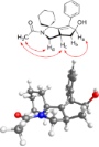
Figure 2: Top: Selected NOE contacts from NOESY 1D spectra of compound 36; bottom: low energy conformer of 36...

Figure 3: PCA plot resulting from the correlation between PC1 vs PC2, showing the positioning in the chemical...

Figure 4: PMI plot showing the skeletal diversity of compounds 3–39 (blue diamonds) with respect to the refer...
Extension of the 5-alkynyluridine side chain via C–C-bond formation in modified organometallic nucleosides using the Nicholas reaction
- Renata Kaczmarek,
- Dariusz Korczyński,
- James R. Green and
- Roman Dembinski
Beilstein J. Org. Chem. 2020, 16, 1–8, doi:10.3762/bjoc.16.1
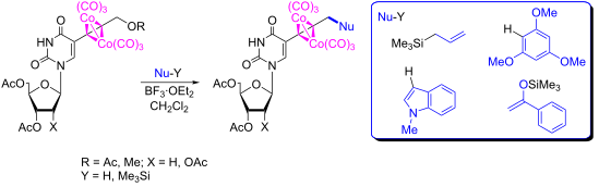
- of alkynyl nucleosides 2 and 3 were confirmed by 1H and 13C NMR spectroscopy and high-resolution mass spectrometry [64][65]. The conversion of alkynyl nucleosides 2 and 3 into the corresponding dicobalt hexacarbonyl nucleosides complexes of 4 and 5 was accomplished at room temperature (Co2(CO)8, THF
- reappearance upfield in the reaction products (i.e., 3.17 ppm in 6a and 4.27 ppm in 6b). In the 13C NMR spectra, the slightly broadened resonance of the metal carbonyl carbons at 199–200 ppm (199.4 ppm in both 6a and 6b) were characteristic of the product alkyne–Co2(CO)6 complexes. In the IR spectra, the
- the synthesis of hexacarbonyl dicobalt 5-alkynyluridines (4 or 5): A round-bottom flask was charged under a nitrogen atmosphere with Co2(CO)8 (0.222 g, 0.650 mmol), alkynyl nucleoside 2 or 3 (0.500 mmol), and THF (10 mL). The mixture was stirred at room temperature (22 °C) for 1 h. The solvent was

Graphical Abstract

Scheme 1: Preparation of (2'-deoxy)-5-alkynyluridines 2 and 3, their dicobalt hexacarbonyl derivatives 4 and 5...
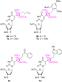
Figure 1: Structures of nucleosides 6 and 7, products of the Nicholas reaction.
Palladium-catalyzed Sonogashira coupling reactions in γ-valerolactone-based ionic liquids
- László Orha,
- József M. Tukacs,
- László Kollár and
- László T. Mika
Beilstein J. Org. Chem. 2019, 15, 2907–2913, doi:10.3762/bjoc.15.284
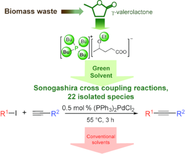
- into Class 2, of which applications should be strictly limited, particularly in pharmaceutical industry. To develop an environmentally benign alternative of this useful method, the reaction has been extended to green solvents such as water [16], fluorous solvents [17], supercritical CO2 [18], and very

Graphical Abstract

Scheme 1: Palladium-catalyzed Sonogashira cross-coupling of iodobenzene (1a) and phenylacetylene (2a) in ioni...

Figure 1: Effect of catalyst precursors used in Sonogashira coupling reaction of iodobenzene (1a, 0.5 mmol) a...

Figure 2: Re-use of Pd catalyst for Sonogashira coupling of iodobenzene (1a) and phenylacetylene (2a). Reacti...