

Search results
Search for "catalytic activity" in Full Text gives 327 result(s) in Beilstein Journal of Organic Chemistry. Showing first 200.
A comprehensive review of flow chemistry techniques tailored to the flavours and fragrances industries
- Guido Gambacorta,
- James S. Sharley and
- Ian R. Baxendale
Beilstein J. Org. Chem. 2021, 17, 1181–1312, doi:10.3762/bjoc.17.90
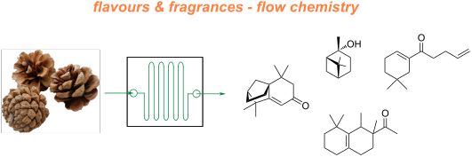

Graphical Abstract

Figure 1: Representative shares of the global F&F market (2018) segmented on their applications [1].

Figure 2: General structure of an international fragrance company [2].

Figure 3: The Michael Edwards fragrance wheel.

Figure 4: Examples of oriental (1–3), woody (4–7), fresh (8–10), and floral (11 and 12) notes.

Figure 5: A basic depiction of batch vs flow.

Scheme 1: Examples of reactions for which flow processing outperforms batch.

Scheme 2: Some industrially important aldol-based transformations.

Scheme 3: Biphasic continuous aldol reactions of acetone and various aldehydes.

Scheme 4: Aldol synthesis of 43 in flow using LiHMDS as the base.

Scheme 5: A semi-continuous synthesis of doravirine (49) involving a key aldol reaction.

Scheme 6: Enantioselective aldol reaction using 5-(pyrrolidin-2-yl)tetrazole (51) as catalyst in a microreact...

Scheme 7: Gröger's example of asymmetric aldol reaction in aqueous media.

Figure 6: Immobilised reagent column reactor types.

Scheme 8: Photoinduced thiol–ene coupling preparation of silica-supported 5-(pyrrolidin-2-yl)tetrazole 63 and...

Scheme 9: Continuous-flow approach for enantioselective aldol reactions using the supported catalyst 67.

Scheme 10: Ötvös’ employment of a solid-supported peptide aldol catalyst in flow.

Scheme 11: The use of proline tetrazole packed in a column for aldol reaction between cyclohexanone (65) and 2...

Scheme 12: Schematic diagram of an aminosilane-grafted Si-Zr-Ti/PAI-HF reactor for continuous-flow aldol and n...

Scheme 13: Continuous-flow condensation for the synthesis of the intermediate 76 to nabumetone (77) and Microi...

Scheme 14: Synthesis of ψ-Ionone (80) in continuous-flow via aldol condensation between citral (79) and aceton...

Scheme 15: Synthesis of β-methyl-ionones (83) from citral (79) in flow. The steps are separately described, an...

Scheme 16: Continuous-flow synthesis of 85 from 84 described by Gavriilidis et al.

Scheme 17: Continuous-flow scCO2 apparatus for the synthesis of 2-methylpentanal (87) and the self-condensed u...

Scheme 18: Chen’s two-step flow synthesis of coumarin (90).

Scheme 19: Pechmann condensation for the synthesis of 7-hydroxyxcoumarin (93) in flow. The setup extended to c...

Scheme 20: Synthesis of the dihydrojasmonate 35 exploiting nitro derivative proposed by Ballini et al.

Scheme 21: Silica-supported amines as heterogeneous catalyst for nitroaldol condensation in flow.

Scheme 22: Flow apparatus for the nitroaldol condensation of p-hydroxybenzaldehyde (102) to nitrostyrene 103 a...

Scheme 23: Nitroaldol reaction of 64 to 105 employing a quaternary ammonium functionalised PANF.

Scheme 24: Enantioselective nitroaldol condensation for the synthesis of 108 under flow conditions.

Scheme 25: Enatioselective synthesis of 1,2-aminoalcohol 110 via a copper-catalysed nitroaldol condensation.

Scheme 26: Examples of Knoevenagel condensations applied for fragrance components.

Scheme 27: Flow apparatus for Knoevenagel condensation described in 1989 by Venturello et al.

Scheme 28: Knoevenagel reaction using a coated multichannel membrane microreactor.

Scheme 29: Continuous-flow apparatus for Knoevenagel condensation employing sugar cane bagasse as support deve...

Scheme 30: Knoevenagel reaction for the synthesis of 131–135 in flow using an amine-functionalised silica gel. ...

Scheme 31: Continuous-flow synthesis of compound 137, a key intermediate for the synthesis of pregabalin (138)...
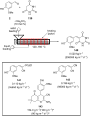
Scheme 32: Continuous solvent-free apparatus applied for the synthesis of compounds 140–143 using a TSE. Throu...

Scheme 33: Lewis et al. developed a spinning disc reactor for Darzens condensation of 144 and a ketone to furn...

Scheme 34: Some key industrial applications of conjugate additions in the F&F industry.

Scheme 35: Continuous-flow synthesis of 4-(2-hydroxyethyl)thiomorpholine 1,1-dioxide (156) via double conjugat...

Scheme 36: Continuous-flow system for Michael addition using CsF on alumina as the catalyst.

Scheme 37: Calcium chloride-catalysed asymmetric Michael addition using an immobilised chiral ligand.

Scheme 38: Continuous multistep synthesis for the preparation of (R)-rolipram (173). Si-NH2: primary amine-fun...

Scheme 39: Continuous-flow Michael addition using ion exchange resin Amberlyst® A26.

Scheme 40: Preparation of the heterogeneous catalyst 181 developed by Paixão et al. exploiting Ugi multicompon...

Scheme 41: Continuous-flow system developed by the Paixão’s group for the preparation of Michael asymmetric ad...

Scheme 42: Continuous-flow synthesis of nitroaldols catalysed by supported catalyst 184 developed by Wennemers...

Scheme 43: Heterogenous polystyrene-supported catalysts developed by Pericàs and co-workers.

Scheme 44: PANF-supported pyrrolidine catalyst for the conjugate addition of cyclohexanone (65) and trans-β-ni...

Scheme 45: Synthesis of (−)-paroxetine precursor 195 developed by Ötvös, Pericàs, and Kappe.

Scheme 46: Continuous-flow approach for the 5-step synthesis of (−)-oseltamivir (201) as devised by Hayashi an...

Scheme 47: Continuous-flow enzyme-catalysed Michael addition.

Scheme 48: Continuous-flow copper-catalysed 1,4 conjugate addition of Grignard reagents to enones. Reprinted w...

Scheme 49: A collection of commonly encountered hydrogenation reactions.

Figure 7: The ThalesNano H-Cube® continuous-flow hydrogenator.

Scheme 50: Chemoselective reduction of an α,β-unsaturated ketone using the H-Cube® reactor.

Scheme 51: Incorporation of Lindlar’s catalyst into the H-Cube® reactor for the reduction of an alkyne.

Scheme 52: Continuous-flow semi-hydrogenation of alkyne 208 to 209 using SACs with H-Cube® system.

Figure 8: The standard setups for tube-in-tube gas–liquid reactor units.

Scheme 53: Homogeneous hydrogenation of olefins using a tube-in-tube reactor setup.
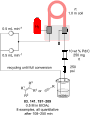
Scheme 54: Recyclable heterogeneous flow hydrogenation system.

Scheme 55: Leadbeater’s reverse tube-in-tube hydrogenation system for olefin reductions.

Scheme 56: a) Hydrogenation using a Pd-immobilised microchannel reactor (MCR) and b) a representation of the i...

Scheme 57: Hydrogenation of alkyne 238 exploiting segmented flow in a Pd-immobilised capillary reactor.

Scheme 58: Continuous hydrogenation system for the preparation of cyrene (241) from (−)-levoglucosenone (240).

Scheme 59: Continuous hydrogenation system based on CSMs developed by Hornung et al.

Scheme 60: Chemoselective reduction of carbonyls (ketones over aldehydes) in flow.

Scheme 61: Continuous system for the semi-hydrogenation of 256 and 258, developed by Galarneau et al.

Scheme 62: Continuous synthesis of biodiesel fuel 261 from lignin-derived furfural acetone (260).

Scheme 63: Continuous synthesis of γ-valerolacetone (263) via CTH developed by Pineda et al.

Scheme 64: Continuous hydrogenation of lignin-derived biomass (products 265, 266, and 267) using a sustainable...

Scheme 65: Ru/C or Rh/C-catalysed hydrogenation of arene in flow as developed by Sajiki et al.

Scheme 66: Polysilane-immobilized Rh–Pt-catalysed hydrogenation of arenes in flow by Kobayashi et al.

Scheme 67: High-pressure in-line mixing of H2 for the asymmetric reduction of 278 at pilot scale with a 73 L p...
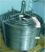
Figure 9: Picture of the PFR employed at Eli Lilly & Co. for the continuous hydrogenation of 278 [287]. Reprinted ...

Scheme 68: Continuous-flow asymmetric hydrogenation using Oppolzer's sultam 280 as chiral auxiliary.
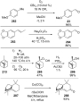
Scheme 69: Some examples of industrially important oxidation reactions in the F&F industry. CFL: compact fluor...

Scheme 70: Gold-catalysed heterogeneous oxidation of alcohols in flow.
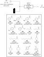
Scheme 71: Uozumi’s ARP-Pt flow oxidation protocol.

Scheme 72: High-throughput screening of aldehyde oxidation in flow using an in-line GC.

Scheme 73: Permanganate-mediated Nef oxidation of nitroalkanes in flow with the use of in-line sonication to p...

Scheme 74: Continuous-flow aerobic anti-Markovnikov Wacker oxidation.

Scheme 75: Continuous-flow oxidation of 2-benzylpyridine (312) using air as the oxidant.

Scheme 76: Continuous-flow photo-oxygenation of monoterpenes.

Scheme 77: A tubular reactor design for flow photo-oxygenation.

Scheme 78: Glucose oxidase (GOx)-mediated continuous oxidation of glucose using compressed air and the FFMR re...

Scheme 79: Schematic continuous-flow sodium hypochlorite/TEMPO oxidation of alcohols.

Scheme 80: Oxidation using immobilised TEMPO (344) was developed by McQuade et al.

Scheme 81: General protocol for the bleach/catalytic TBAB oxidation of aldehydes and alcohols.

Scheme 82: Continuous-flow PTC-assisted oxidation using hydrogen peroxide. The process was easily scaled up by...

Scheme 83: Continuous-flow epoxidation of cyclohexene (348) and in situ preparation of m-CPBA.

Scheme 84: Continuous-flow epoxidation using DMDO as oxidant.

Scheme 85: Mukayama aerobic epoxidation optimised in flow mode by the Favre-Réguillon group.

Scheme 86: Continuous-flow asymmetric epoxidation of derivatives of 359 exploiting a biomimetic iron catalyst.

Scheme 87: Continuous-flow enzymatic epoxidation of alkenes developed by Watts et al.

Scheme 88: Engineered multichannel microreactor for continuous-flow ozonolysis of 366.

Scheme 89: Continuous-flow synthesis of the vitamin D precursor 368 using multichannel microreactors. MFC: mas...

Scheme 90: Continuous ozonolysis setup used by Kappe et al. for the synthesis of various substrates employing ...

Scheme 91: Continuous-flow apparatus for ozonolysis as developed by Ley et al.

Scheme 92: Continuous-flow ozonolysis for synthesis of vanillin (2) using a film-shear flow reactor.

Scheme 93: Examples of preparative methods for ajoene (386) and allicin (388).

Scheme 94: Continuous-flow oxidation of thioanisole (389) using styrene-based polymer-supported peroxytungstat...

Scheme 95: Continuous oxidation of thiosulfinates using Oxone®-packed reactor.

Scheme 96: Continuous-flow electrochemical oxidation of thioethers.

Scheme 97: Continuous-flow oxidation of 400 to cinnamophenone (235).

Scheme 98: Continuous-flow synthesis of dehydrated material 401 via oxidation of methyl dihydrojasmonate (33).

Scheme 99: Some industrially important transformations involving Grignard reagents.

Scheme 100: Grachev et al. apparatus for continuous preparation of Grignard reagents.

Scheme 101: Example of fluidized Mg bed reactor with NMR spectrometer as on-line monitoring system.

Scheme 102: Continuous-flow synthesis of Grignard reagents and subsequent quenching reaction.

Figure 10: Membrane-based, liquid–liquid separator with integrated pressure control [52]. Adapted with permission ...

Scheme 103: Continuous-flow synthesis of 458, an intermediate to fluconazole (459).

Scheme 104: Continuous-flow synthesis of ketones starting from benzoyl chlorides.

Scheme 105: A Grignard alkylation combining CSTR and PFR technologies with in-line infrared reaction monitoring....

Scheme 106: Continuous-flow preparation of 469 from Grignard addition of methylmagnesium bromide.

Scheme 107: Continuous-flow synthesis of Grignard reagents 471.

Scheme 108: Preparation of the Grignard reagent 471 using CSTR and the continuous process for synthesis of the ...

Scheme 109: Continuous process for carboxylation of Grignard reagents in flow using tube-in-tube technology.

Scheme 110: Continuous synthesis of propargylic alcohols via ethynyl-Grignard reagent.

Scheme 111: Silica-supported catalysed enantioselective arylation of aldehydes using Grignard reagents in flow ...

Scheme 112: Acid-catalysed rearrangement of citral and dehydrolinalool derivatives.

Scheme 113: Continuous stilbene isomerisation with continuous recycling of photoredox catalyst.

Scheme 114: Continuous-flow synthesis of compound 494 as developed by Ley et al.

Scheme 115: Selected industrial applications of DA reaction.

Scheme 116: Multistep flow synthesis of the spirocyclic structure 505 via employing DA cycloaddition.

Scheme 117: Continuous-flow DA reaction developed in a plater flow reactor for the preparation of the adduct 508...

Scheme 118: Continuous-flow DA reaction using a silica-supported imidazolidinone organocatalyst.

Scheme 119: Batch vs flow for the DA reaction of (cyclohexa-1,5-dien-1-yloxy)trimethylsilane (513) with acrylon...

Scheme 120: Continuous-flow DA reaction between 510 and 515 using a shell-core droplet system.

Scheme 121: Continuous-flow synthesis of bicyclic systems from benzyne precursors.

Scheme 122: Continuous-flow synthesis of bicyclic scaffolds 527 and 528 for further development of potential ph...

Scheme 123: Continuous-flow inverse-electron hetero-DA reaction to pyridine derivatives such as 531.

Scheme 124: Comparison between batch and flow for the synthesis of pyrimidinones 532–536 via retro-DA reaction ...

Scheme 125: Continuous-flow coupled with ultrasonic system for preparation of ʟ-ascorbic acid derivatives 539 d...

Scheme 126: Two-step continuous-flow synthesis of triazole 543.

Scheme 127: Continuous-flow preparation of triazoles via CuAAC employing 546-based heterogeneous catalyst.

Scheme 128: Continuous-flow synthesis of compounds 558 through A3-coupling and 560 via AgAAC both employing the...

Scheme 129: Continuous-flow photoinduced [2 + 2] cycloaddition for the preparation of bicyclic derivatives of 5...

Scheme 130: Continuous-flow [2 + 2] and [5 + 2] cycloaddition on large scale employing a flow reactor developed...

Scheme 131: Continuous-flow preparation of the tricyclic structures 573 and 574 starting from pyrrole 570 via [...

Scheme 132: Continuous-flow [2 + 2] photocyclization of cinnamates.

Scheme 133: Continuous-flow preparation of cyclobutane 580 on a 5-plates photoreactor.

Scheme 134: Continuous-flow [2 + 2] photocycloaddition under white LED lamp using heterogeneous PCN as photocat...

Figure 11: Picture of the parallel tube flow reactor (PTFR) "The Firefly" developed by Booker-Milburn et al. a...

Scheme 135: Continuous-flow acid-catalysed [2 + 2] cycloaddition between silyl enol ethers and acrylic esters.

Scheme 136: Continuous synthesis of lactam 602 using glass column reactors.

Scheme 137: In situ generation of ketenes for the Staudinger lactam synthesis developed by Ley and Hafner.

Scheme 138: Application of [2 + 2 + 2] cycloadditions in flow employed by Ley et al.

Scheme 139: Examples of FC reactions applied in F&F industry.

Scheme 140: Continuous-flow synthesis of ibuprofen developed by McQuade et al.

Scheme 141: The FC acylation step of Jamison’s three-step ibuprofen synthesis.

Scheme 142: Synthesis of naphthalene derivative 629 via FC acylation in microreactors.

Scheme 143: Flow system for rapid screening of catalysts and reaction conditions developed by Weber et al.

Scheme 144: Continuous-flow system developed by Buorne, Muller et al. for DSD optimisation of the FC acylation ...

Scheme 145: Continuous-flow FC acylation of alkynes to yield β-chlorovinyl ketones such as 638.

Scheme 146: Continuous-flow synthesis of tonalide (619) developed by Wang et al.

Scheme 147: Continuous-flow preparation of acylated arene such as 290 employing Zr4+-β-zeolite developed by Kob...

Scheme 148: Flow system applied on an Aza-FC reaction catalysed by the thiourea catalyst 648.

Scheme 149: Continuous hydroformylation in scCO2.

Scheme 150: Two-step flow synthesis of aldehyde 655 through a sequential Heck reaction and subsequent hydroform...

Scheme 151: Single-droplet (above) and continuous (below) flow reactors developed by Abolhasani et al. for the ...

Scheme 152: Continuous hydroformylation of 1-dodecene (655) using a PFR-CSTR system developed by Sundmacher et ...

Scheme 153: Continuous-flow synthesis of the aldehyde 660 developed by Eli Lilly & Co. [32]. Adapted with permissio...

Scheme 154: Continuous asymmetric hydroformylation employing heterogenous catalst supported on carbon-based sup...

Scheme 155: Examples of acetylation in F&F industry: synthesis of bornyl (S,R,S-664) and isobornyl (S,S,S-664) ...

Scheme 156: Continuous-flow preparation of bornyl acetate (S,R,S-664) employing the oscillating flow reactor.

Scheme 157: Continuous-flow synthesis of geranyl acetate (666) from acetylation of geraniol (343) developed by ...

Scheme 158: 12-Ttungstosilicic acid-supported silica monolith-catalysed acetylation in flow.

Scheme 159: Continuous-flow preparation of cyclopentenone 676.

Scheme 160: Two-stage synthesis of coumarin (90) via acetylation of salicylaldehyde (88).

Scheme 161: Intensification process for acetylation of 5-methoxytryptamine (677) to melatonin (678) developed b...

Scheme 162: Examples of macrocyclic musky odorants both natural (679–681) and synthetic (682 and 683).

Scheme 163: Flow setup combined with microwave for the synthesis of macrocycle 686 via RCM.

Scheme 164: Continuous synthesis of 2,5-dihydro-1H-pyrroles via ring-closing metathesis.

Scheme 165: Continuous-flow metathesis of 485 developed by Leadbeater et al.

Figure 12: Comparison between RCM performed using different routes for the preparation of 696. On the left the...

Scheme 166: Continuous-flow RCM of 697 employed the solid-supported catalyst 698 developed by Grela, Kirschning...

Scheme 167: Continuous-flow RORCM of cyclooctene employing the silica-absorbed catalyst 700.

Scheme 168: Continuous-flow self-metathesis of methyl oleate (703) employing SILP catalyst 704.

Scheme 169: Flow apparatus for the RCM of 697 using a nanofiltration membrane for the recovery and reuse of the...

Scheme 170: Comparison of loadings between RCMs performed with different routes for the synthesis of 709.
Heterogeneous photocatalytic cyanomethylarylation of alkenes with acetonitrile: synthesis of diverse nitrogenous heterocyclic compounds
- Guanglong Pan,
- Qian Yang,
- Wentao Wang,
- Yurong Tang and
- Yunfei Cai
Beilstein J. Org. Chem. 2021, 17, 1171–1180, doi:10.3762/bjoc.17.89
- ). Traditional g-C3N4 exhibited a low catalytic activity for this transformation (Table 1, entry 6). Switching from CN-K to a homogeneous organo photocatalyst such as eosin Y and 4CzIPN, led to lower yields of the desired product (Table 1, entries 7 and 8). The expensive Ru/Ir-based metal complexes gave similar

Graphical Abstract

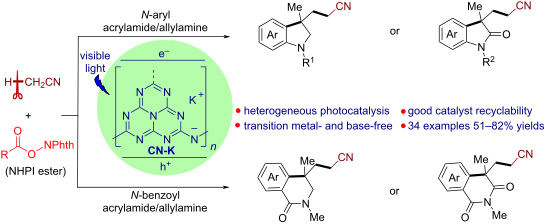
Scheme 1: CN-K-Catalyzed cyanomethylarylation of alkenes to access diverse heterocyclic compounds.

Scheme 2: CN-K-catalyzed cyanomethylarylation of N-arylallylamines for the synthesis of indolines. Reaction c...

Scheme 3: CN-K-catalyzed cyanomethylarylation of N-benzoylallylamines for the synthesis of isoquinolinones. R...

Scheme 4: CN-K-catalyzed cyanomethylarylation of N-aryl acrylamides for the synthesis of oxindoles. Reaction ...

Scheme 5: CN-K-catalyzed cyanomethylarylation of N-benzoyl acrylamides for the synthesis of isoquinolinedione...

Figure 1: Evaluation of catalyst recycling. Reaction conditions: 1a (0.1 mmol, 1 equiv), 2d (0.2 mmol, 2 equi...

Scheme 6: Further survey of reaction scope and derivatization studies of 8a.

Scheme 7: Experiments for the mechanistic study.

Scheme 8: Plausible mechanism of the CN-K-catalyzed cyanomethylarylation of alkenes.
Recent advances in palladium-catalysed asymmetric 1,4–additions of arylboronic acids to conjugated enones and chromones
- Jan Bartáček,
- Jan Svoboda,
- Martin Kocúrik,
- Jaroslav Pochobradský,
- Alexander Čegan,
- Miloš Sedlák and
- Jiří Váňa
Beilstein J. Org. Chem. 2021, 17, 1048–1085, doi:10.3762/bjoc.17.84
- increased the catalytic activity and allowed to run the reaction at a lower temperature [48]. This can be very useful for substrates that can react with traces of Pd(0) that are formed by minor side reactions. The authors suspected that hexafluorophosphate anions stabilize the cationic Pd species and result
- achieving a higher ee, however, it also caused a faster loss of catalytic activity. Later in 2020, Zhou et al. used an analogous heterogeneous system as O’Reilly (cf. Table 28) [56][58]. A RAFT polymerisation reaction, in this case, led to a polymeric backbone with terminal catalytic centres [58] (Scheme 20

Graphical Abstract

Scheme 1: Synthesis of optically pure 4-phenylchroman-2-one [34].

Scheme 2: Synthesis of (R)-tolterodine [3].

Scheme 3: Catalytic cycle of the Pd(II)-catalysed 1,4-addition of organoboron reagents to enones [3,26,35].

Scheme 4: Enantioselective β-arylation of cyclohexanone [38].

Scheme 5: Application of L2/Pd(OAc)2 in the total synthesis of terpenes [8].
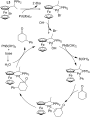
Scheme 6: Plausible catalytic cycle for the addition of phenylboronic acid to 2-cyclohexenone catalysed by L3...

Scheme 7: Microwave-assisted addition of phenylboronic acid to 2-cyclohexenone catalysed by L4/Pd2(dba)3·CHCl3...
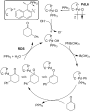
Scheme 8: Plausible catalytic cycle of the addition of phenylboronic acid to 2-cyclohexenone catalysed by pal...
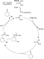
Scheme 9: Proposed catalytic cycle for the addition of phenylboronic acids to 2-cyclohexenone catalysed by Pd...

Scheme 10: Usage of addition reactions of boronic acids to various chromones in the syntheses of potentially a...

Scheme 11: Multigram-scale synthesis of ABBV-2222 [6].

Scheme 12: Application of the asymmetric addition of phenylboronic acid to a chromone derivative for the total...

Scheme 13: Plausible catalytic cycle for the addition of phenylboronic acid to 3-methyl-2-cyclohexenone cataly...

Scheme 14: Total syntheses of naturally occurring terpenoids [10,11].

Scheme 15: Use of the L9/Pd(TFA)2 catalytic system for the synthesis of intermediates of biologically active c...

Scheme 16: Usage of a Michael addition catalysed by L9/Pd(TFA)2 in the total synthesis of (–)-ar-tenuifolene [12].

Scheme 17: Synthesis of terpenoids by Michael addition to 3-methyl-2-cyclopentenone [13].

Scheme 18: Rh-catalysed isomerisation of 3-alkyl-3-arylcyclopentanones to 1-tetralones [53].

Scheme 19: Addition reaction of phenylboronic acid to 3-methyl-2-cyclohexenone catalysed by L9/Pd(TFA)2 in wat...

Scheme 20: Micellar nanoreactor PdL10c for the synthesis of flavanones [58].
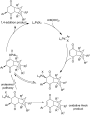
Scheme 21: Plausible catalytic cycle for the desymmetrisation of polycyclic cyclohexenediones by the addition ...

Scheme 22: Attempt to use the catalytic system L2/Pd(TFA)2 for the addition of phenylboronic acid to 3-methyl-...

Scheme 23: Ring opening of an enantioenriched tetrahydropyran-2-one derivative as alternative strategy to line...

Scheme 24: Synthesis of biologically active compounds from addition products [14-16].

Scheme 25: Chiral 1,10-phenantroline derivative L15 as ligand for the Pd-catalysed addition reactions of pheny...

Scheme 26: The Rh-catalysed addition reaction of phenylboronic acid to a 3-substituted enone [20].
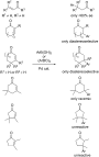
Scheme 27: Underdeveloped methodologies [14,15,65-67].
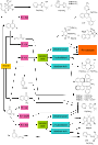
Scheme 28: Flowchart for the selection of the proper catalytic system.
Highly regio- and stereoselective phosphinylphosphination of terminal alkynes with tetraphenyldiphosphine monoxide under radical conditions
- Dat Phuc Tran,
- Yuki Sato,
- Yuki Yamamoto,
- Shin-ichi Kawaguchi,
- Shintaro Kodama,
- Akihiro Nomoto and
- Akiya Ogawa
Beilstein J. Org. Chem. 2021, 17, 866–872, doi:10.3762/bjoc.17.72
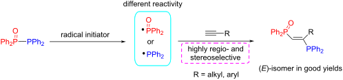
- synthetic method for the highly selective synthesis of the (E)- or (Z)-isomers is strongly desired [27][28][29][30]. Furthermore, since it was reported that the introduction of a substituent into the ethylene moiety has a great effect on the catalytic activity [31], it is considered important to synthesize

Graphical Abstract
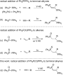
Scheme 1: Radical addition of Ph2PPPh2 and Ph2P(X)PPh2 to unsaturated C–C bonds.

Scheme 2: The addition of Ph2P(O)PPh2 (1) to 1-octyne (2a).

Scheme 3: Phosphinylphosphination of various terminal alkynes 2 with 1. aIsolated yields. V-40 = 1,1’-azobis(...

Scheme 4: Attempted radical addition to internal alkynes and insight into the addition to 2n.

Scheme 5: A plausible reaction pathway for the radical addition of Ph2P(O)PPh2 to terminal alkynes.
Microwave-assisted multicomponent reactions in heterocyclic chemistry and mechanistic aspects
- Shivani Gulati,
- Stephy Elza John and
- Nagula Shankaraiah
Beilstein J. Org. Chem. 2021, 17, 819–865, doi:10.3762/bjoc.17.71
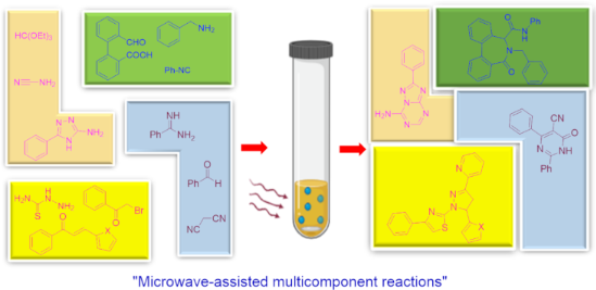

Graphical Abstract

Figure 1: Marketed drugs with acridine moiety.

Scheme 1: Synthesis of 4-arylacridinediones.

Scheme 2: Proposed mechanism for acridinedione synthesis.

Scheme 3: Synthesis of tetrahydrodibenzoacridinones.

Scheme 4: Synthesis of naphthoacridines.

Scheme 5: Plausible mechanism for naphthoacridines.
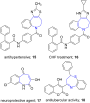
Figure 2: Benzoazepines based potent molecules.

Scheme 6: Synthesis of azepinone.

Scheme 7: Proposed mechanism for azepinone formation.

Scheme 8: Synthesis of benzoazulenen-1-one derivatives.

Scheme 9: Proposed mechanism for benzoazulene-1-one synthesis.

Figure 3: Indole-containing pharmacologically active molecules.

Scheme 10: Synthesis of functionalized indoles.

Scheme 11: Plausible mechanism for the synthesis of functionalized indoles.

Scheme 12: Synthesis of spirooxindoles.

Scheme 13: Synthesis of substituted spirooxindoles.

Scheme 14: Plausible mechanism for the synthesis of substituted spirooxindoles.

Scheme 15: Synthesis of pyrrolidinyl spirooxindoles.

Scheme 16: Proposed mechanism for pyrrolidinyl spirooxindoles.

Figure 4: Pyran-containing biologically active molecules.

Scheme 17: Synthesis of functionalized benzopyrans.

Scheme 18: Plausible mechanism for synthesis of benzopyran.

Scheme 19: Synthesis of indoline-spiro-fused pyran derivatives.

Scheme 20: Proposed mechanism for indoline-spiro-fused pyran.

Scheme 21: Synthesis of substituted naphthopyrans.

Figure 5: Marketed drugs with pyrrole ring.

Scheme 22: Synthesis of tetra-substituted pyrroles.

Scheme 23: Mechanism for silica-supported PPA-SiO2-catalyzed pyrrole synthesis.

Scheme 24: Synthesis of pyrrolo[1,10]-phenanthrolines.

Scheme 25: Proposed mechanism for pyrrolo[1,10]-phenanthrolines.

Figure 6: Marketed drugs and molecules containing pyrimidine and pyrimidinones skeletons.

Scheme 26: MWA-MCR pyrimidinone synthesis.

Scheme 27: Two proposed mechanisms for pyrimidinone synthesis.

Scheme 28: MWA multicomponent synthesis of dihydropyrimidinones.

Scheme 29: Proposed mechanism for dihydropyrimidinones.

Figure 7: Biologically active fused pyrimidines.

Scheme 30: MWA- MCR for the synthesis of pyrrolo[2,3-d]pyrimidines.

Scheme 31: Proposed mechanism for pyrrolo[2,3-d]pyrimidines.

Scheme 32: Synthesis of substituted pyrrolo[2,3-d]pyrimidine-2,4-diones.

Scheme 33: Probable pathway for pyrrolo[2,3-d]pyrimidine-2,4-diones.

Scheme 34: Synthesis of pyridopyrimidines.

Scheme 35: Plausible mechanism for the synthesis of pyridopyrimidines.

Scheme 36: Synthesis of dihydropyridopyrimidine and dihydropyrazolopyridine.

Scheme 37: Proposed mechanism for the formation of dihydropyridopyrimidine.

Scheme 38: Synthesis of thiopyrano[4,3-d]pyrimidines.

Scheme 39: Plausible mechanism for the synthesis of thiopyrano[4,3-d]pyrimidines.

Scheme 40: Synthesis of decorated imidazopyrimidines.

Scheme 41: Proposed mechanism for imidazopyrimidine synthesis.

Figure 8: Pharmacologically active molecules containing purine bases.

Scheme 42: Synthesis of aza-adenines.

Scheme 43: Synthesis of 5-aza-7-deazapurines.
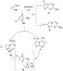
Scheme 44: Proposed mechanism for deazapurines synthesis.

Figure 9: Biologically active molecules containing pyridine moiety.

Scheme 45: Synthesis of steroidal pyridines.

Scheme 46: Proposed mechanism for steroidal pyridine.

Scheme 47: Synthesis of N-alkylated 2-pyridones.

Scheme 48: Two possible mechanisms for pyridone synthesis.

Scheme 49: Synthesis of pyridone derivatives.

Scheme 50: Postulated mechanism for synthesis of pyridone.

Figure 10: Biologically active fused pyridines.

Scheme 51: Benzimidazole-imidazo[1,2-a]pyridines synthesis.

Scheme 52: Mechanism for the synthesis of benzimidazole-imidazo[1,2-a]pyridines.

Scheme 53: Synthesis of pyrazolo[3,4-b]pyridine-5-spirocycloalkanedione derivatives.

Scheme 54: Proposed mechanism for spiro-pyridines.

Scheme 55: Functionalized macrocyclane-fused pyrazolo[3,4-b]pyridine derivatives.

Scheme 56: Mechanism postulated for macrocyclane-fused pyrazolo[3,4-b]pyridine.

Scheme 57: Generation of pyrazolo[3,4-b]pyridines.

Scheme 58: Proposed mechanism for the synthesis of pyrazolo[3,4-b]pyridines.

Scheme 59: Proposed mechanism for the synthesis of azepinoindole.

Figure 11: Pharmaceutically important molecules with quinoline moiety.

Scheme 60: Povarov-mediated quinoline synthesis.

Scheme 61: Proposed mechanism for Povarov reaction.

Scheme 62: Synthesis of pyrazoloquinoline.

Scheme 63: Plausible mechanism for pyrazoloquinoline synthesis.

Figure 12: Quinazolinones as pharmacologically significant scaffolds.

Scheme 64: Four-component reaction for dihydroquinazolinone.

Scheme 65: Proposed mechanism for dihydroquinazolinones.

Scheme 66: Synthesis purine quinazolinone and PI3K-δ inhibitor.

Scheme 67: Synthesis of fused benzothiazolo/benzoimidazoloquinazolinones.

Scheme 68: Proposed mechanism for fused benzothiazolo/benzoimidazoloquinazolinones.

Scheme 69: On-water reaction for synthesis of thiazoloquinazolinone.

Scheme 70: Proposed mechanism for the thiazoloquinazolinone synthesis.

Scheme 71: β-Cyclodextrin-mediated synthesis of indoloquinazolinediones.

Scheme 72: Proposed mechanism for synthesis of indoloquinazolinediones.

Figure 13: Triazoles-containing marketted drugs and pharmacologically active molecules.

Scheme 73: Cu(I) DAPTA-catalyzed 1,2,3-triazole formation.

Scheme 74: Mechanism for Cu(I) DAPTA-catalyzed triazole formation.

Scheme 75: Synthesis of β-hydroxy-1,2,3-triazole.

Scheme 76: Proposed mechanism for synthesis of β-hydroxy-1,2,3-triazoles.

Scheme 77: Synthesis of bis-1,2,4-triazoles.

Scheme 78: Proposed mechanism for bis-1,2,4-triazoles synthesis.

Figure 14: Thiazole containing drugs.

Scheme 79: Synthesis of a substituted thiazole ring.

Scheme 80: Synthesis of pyrazolothiazoles.

Figure 15: Chromene containing drugs.

Scheme 81: Magnetic nanocatalyst-mediated aminochromene synthesis.

Scheme 82: Proposed mechanism for the synthesis of chromenes.
Valorisation of plastic waste via metal-catalysed depolymerisation
- Francesca Liguori,
- Carmen Moreno-Marrodán and
- Pierluigi Barbaro
Beilstein J. Org. Chem. 2021, 17, 589–621, doi:10.3762/bjoc.17.53
- (dicyclophosphino)ethane) showed minimal improvements compared to the chloride salt catalyst [205]. The use of transition metal-substituted polyoxometallates (POMs), of the general formula K6SiW11MO39(H2O) (M = Zn2+, Mn2+, Co2+, Cu2+, Ni2+) [206][207], was also investigated [208]. The catalytic activity was found
- compared to 2D materials, thanks to a typical 8–16 nm outer diameter tubular morphology [215][216] and the potential for facile metal doping via ion-exchange of the solid support [217][218]. Lewis acid-type catalytic activity was also postulated for γ-Fe2O3 NPs, which provided BHET in 90% yield at 300 °C
- [ZnCl3] (bmim = 1-butyl-3-methylimidazolium, Table 4, entry 2) [228] were recently studied, showing higher catalytic activity compared to metal-free ionic liquids (i.e., bmim chloride), the conventional catalysts (i.e., ZnCl2, Zn(OAc)2) or the analogous Mn, Co and Cu ionic liquids. Typically, 80–85% BHET

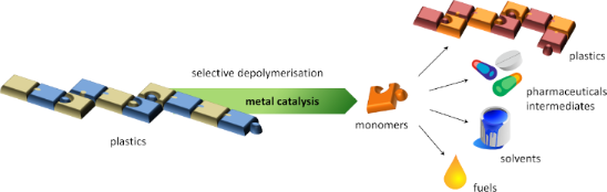
Graphical Abstract

Figure 1: Potential classification of plastic recycling processes. The area covered by the present review is ...

Figure 2: EG produced during glycolytic depolymerisation of PET using DEG + DPG as solvent and titanium(IV) n...

Scheme 1: Simplified representation of the conversion of 1,4-PBD to C16–C44 macrocycles using Ru metathesis c...
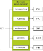
Figure 3: Main added-value monomers obtainable by catalytic depolymerisation of PET via chemolytic methods.

Scheme 2: Hydrogenolytic depolymerisation of PET by ruthenium complexes.

Scheme 3: Depolymerisation of PET via catalytic hydrosilylation by Ir(III) pincer complex.

Scheme 4: Catalytic hydrolysis (top) and methanolysis (bottom) reactions of PET.

Scheme 5: Depolymerisation of PET by glycolysis with ethylene glycol.

Figure 4: Glycolysis of PET: evolution of BHET yield over time, with and without zinc acetate catalyst (196 °...

Scheme 6: Potential activated complex for the glycolysis reaction of PET catalysed by metallated ILs and evol...

Scheme 7: One-pot, two-step process for PET repurposing via chemical recycling.
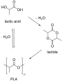
Scheme 8: Synthetic routes to PLA.

Scheme 9: Structures of the zinc molecular catalysts used for PLA-methanolysis in various works. a) See [265], b) ...

Scheme 10: Depolymerisation of PLLA by Zn–N-heterocyclic carbene complex.

Scheme 11: Salalen ligands.

Scheme 12: Catalytic hydrogenolysis of PLA.

Scheme 13: Catalytic hydrosilylation of PLA.

Scheme 14: Hydrogenative depolymerisation of PBT and PCL by molecular Ru catalysts.

Scheme 15: Glycolysis reaction of PCT by diethylene glycol.

Scheme 16: Polymerisation–depolymerisation cycle of 3,4-T6GBL.
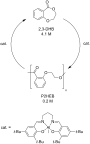
Scheme 17: Polymerisation–depolymerisation cycle of 2,3-HDB.

Scheme 18: Hydrogenative depolymerisation of PBPAC by molecular Ru catalysts.

Scheme 19: Catalytic hydrolysis (top), alcoholysis (middle) and aminolysis (bottom) reactions of PBPAC.

Scheme 20: Hydrogenative depolymerisation of PPC (top) and PEC (bottom) by molecular Ru catalysts.
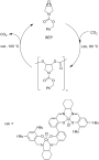
Scheme 21: Polymerisation-depolymerisation cycle of BEP.

Scheme 22: Hydrogenolysis of polyamides using soluble Ru catalysts.

Scheme 23: Catalytic depolymerisation of epoxy resin/carbon fibres composite.

Scheme 24: Depolymerisation of polyethers with metal salt catalysts and acyl chlorides.
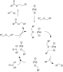
Scheme 25: Proposed mechanism for the iron-catalysed depolymerisation reaction of polyethers. Adapted with per...
Au(III) complexes with tetradentate-cyclam-based ligands
- Ann Christin Reiersølmoen,
- Thomas N. Solvi and
- Anne Fiksdahl
Beilstein J. Org. Chem. 2021, 17, 186–192, doi:10.3762/bjoc.17.18
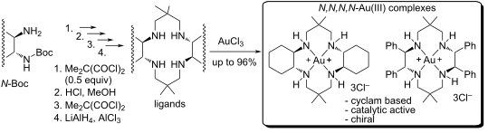
- -membered chelate rings. The testing of the catalytic ability of the cyclam-based N,N,N,N-Au(III) complexes demonstrated high catalytic activity of some complexes in selected test reactions (full conversion in 1–24 h, 62–97% product yields). Keywords: Au(III); carboalkoxylation; coordination studies
- , due to sample decomposition. Attempts to obtain crystals for X-ray analysis by slow diffusion of n-pentane into a DCM solution of the complexes were unsuccessful. Catalytic activity For evaluation of the catalytic ability of the new Au(III) complexes, alkyne carboalkoxylation [47][48] and
- . Evaluation of complex 6b-Au(III) in both reactions, revealed a large difference in catalytic activity and complex stability between the structurally similar 6a-Au(III) and 6b-Au(III) cyclam complexes, with a cyclohexyl and a diphenyl-C2 bridge between the nitrogens, respectively. In both test reactions, an

Graphical Abstract

Scheme 1: Synthetic protocols for the preparation of potential ligands 1–4.

Scheme 2: Reduction of diamides 1a,b and tetraamides 2a,b.

Scheme 3: Au(III) coordination conditions for ligands 5a,b and 6a,b. Coordination of 5b was unsuccessful.

Figure 1: 1H NMR study of the formation of complex 6a-Au(III) by AuCl3 coordination to ligand 6a.
Direct synthesis of anomeric tetrazolyl iminosugars from sugar-derived lactams
- Michał M. Więcław and
- Bartłomiej Furman
Beilstein J. Org. Chem. 2021, 17, 115–123, doi:10.3762/bjoc.17.12
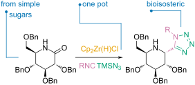
- of this research we have developed a methodology for the synthesis of sugar-derived α-tetrazolylamines. Such compounds – incorporating both iminosugar and tetrazole fragments – are particularly interesting, thanks to the well-known biological and catalytic activity of these moieties. This work is the

Graphical Abstract

Scheme 1: Our previous efforts in the field of functionalization of sugar-derived lactams.

Figure 1: Key concepts behind the goal of this work [34].

Scheme 2: Preliminary experiment in search of a procedure for the synthesis of 2-(1H-tetrazol-5-yl)-iminosuga...

Scheme 3: Synthesis of a new class of alkaloid scaffold using the presented methodology.

Scheme 4: Synthesis of a new, chiral 2-(tetrazol-5-yl)-iminosugar based potential organocatalyst.

Scheme 5: Principle behind Woerpel’s model for prediction of the direction of nucleophile addition to oxocarb...

Scheme 6: Difference in conformational stability of glucose- and galactose-derived iminium cations and the maj...
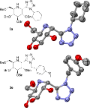
Figure 2: ORTEP structures of compounds 3a and 3e obtained by X-ray analysis. Hydrogen atoms and benzyl group...

Figure 3: Proposed structures of compounds 5a and 2-epi-5a with 1H-1H couplings and NOE effects shown.

Scheme 7: Proposed reaction mechanism for the described Ugi–azide reaction variant.

Scheme 8: Possible pathway for spontaneous imine formation. Values reported are in kcal·mol−1.

Scheme 9: A possible path for tetrazole formation in the described conditions. Values reported are in kcal·mol...
Silver-catalyzed synthesis of β-fluorovinylphosphonates by phosphonofluorination of aromatic alkynes
- Yajing Zhang,
- Qingshan Tian,
- Guozhu Zhang and
- Dayong Zhang
Beilstein J. Org. Chem. 2020, 16, 3086–3092, doi:10.3762/bjoc.16.258
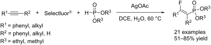
- -fluorovinylphosphonates under mild conditions. First, we examined the catalytic activity of various transition metal catalysts, including Au, Ag, Cu, Rh, and Pd complexes (Supporting Information File 1). Among these metal salts, silver salts, especially AgOAc, were the most effective catalysts for generating the desired

Graphical Abstract
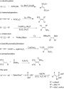
Scheme 1: Metal-catalyzed difunctionalization of unsaturated carbon–carbon bonds.
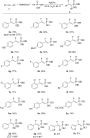
Scheme 2: Substrate scope for the synthesis of the β-fluorovinylphosphonates 2 using diethyl phosphite. React...

Scheme 3: Substrate scope for the synthesis of the β-fluorovinylphosphonates 3 using dimethyl phosphite. Reac...

Scheme 4: Radical-trapping experiments.

Scheme 5: Proposed mechanism for the silver-catalyzed phosphonofluorination of alkynes.

Scheme 6: Attempted use of a suspected phosphonofluorination intermediate to synthesize a β-fluorovinylphosph...
A novel and robust heterogeneous Cu catalyst using modified lignosulfonate as support for the synthesis of nitrogen-containing heterocycles
- Bingbing Lai,
- Meng Ye,
- Ping Liu,
- Minghao Li,
- Rongxian Bai and
- Yanlong Gu
Beilstein J. Org. Chem. 2020, 16, 2888–2902, doi:10.3762/bjoc.16.238
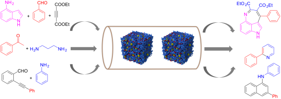
- a robust supporting material to immobilize a copper species. The so-obtained catalyst was characterized by many physicochemical methods including FTIR, EA, FSEM, FTEM, XPS, and TG. This catalyst exhibited excellent catalytic activity in the synthesis of nitrogen-containing heterocycles such as
- spectra were further recorded, and the results confirmed the presence of Cu+ at ≈570 eV, while Cu0 at 565.6 eV [29][30][31], meaning that Cu2+ species were partially reduced during the course of immobilization. Catalytic activity of the catalysts With the catalysts in hand, we investigated their catalytic
- were formed (Table 1, entry 1). After screening different kind of solvents (Table 1, entries 2–8) at 60 °C, EtOH was found to be the best one, and the target product 4a was obtained in 86% yield (Table 1, entry 8). The referential catalysts LS-FM-Cu and Resin-Cu showed inferior catalytic activity for

Graphical Abstract

Figure 1: Schematic illustration for the preparation of the catalyst in this work.

Figure 2: FTIR spectra of LS, LS-FAS, and LS-FAS-Cu.

Figure 3: Thermogravimetric weight loss of the obtained materials LS-FAS and LS-FAS-Cu.

Figure 4: FSEM imagine of LS-FAS-Cu in different scale label a) 1 μm, b) 200 nm; FTEM images of LS-FAS-Cu in ...

Figure 5: XPS spectra of LS-FAS-Cu in the regions of C 1s, O 1s, Cu 2p3/2 and Cu LMM (inset).
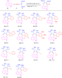
Scheme 1: Substrate scope of LS-FAS-Cu catalyzed three-component reactions of 4-aminoindoles, alkynes and ald...

Figure 6: Recyclability of LS-FAS-Cu, LS-FM-Cu and Resin-Cu in the reaction between compounds 1a, 2a and 3a.
Using multiple self-sorting for switching functions in discrete multicomponent systems
- Amit Ghosh and
- Michael Schmittel
Beilstein J. Org. Chem. 2020, 16, 2831–2853, doi:10.3762/bjoc.16.233
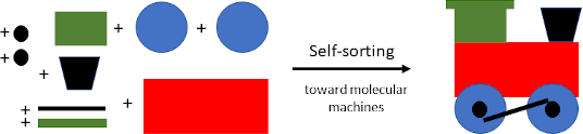
- innovative catch–release system with multiple functions combined the ON/OFF-adjustment of silver(I) catalysis and fluorescence monitoring [59]. Actually, the ratiometric luminescence response allowed the exact monitoring of the catalytic activity. In the initial incomplete self-sorting (state SelfSORT-I
- finding suggested that the catalytic activity in SelfSORT-II was reduced to roughly half of the initial activity in SelfSORT-I. Finally, the addition of two equiv of copper(I) ions generated SelfSORT-III where no additional product was afforded, indicating an OFF state of the catalytic machinery. To
- catalytic activity. In sum, this study demonstrated partial and full release/binding of the organocatalyst 75 during the walking of the biped. Rather recently, the Schmittel group described a precise intermolecular communication system, in which multiple self-sorting steps set up a catalytic AND gate

Graphical Abstract

Figure 1: Some selected self-sorting outcomes and their qualitative and quantitative assessment.

Figure 2: Illustration of an integrative vs a non-integrative self-sorting.

Figure 3: The pH-driven four-component 2-fold completive self-sorting based on host–guest chemistry.

Figure 4: (a) The monomers 5 and 6 and their H-bonding array. (b) The hydrogen-bonded octameric and tetrameri...

Figure 5: (a) Two new Zn4L6-type cages. (b) The encapsulation of C70 induced distinct reconstitutions within ...
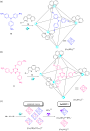
Figure 6: The formation of octahedral cages (a) [Co6(10')4]12+ and (b) [Co6(11')4]12+. (c) The 2-fold complet...

Figure 7: Exchange of Ag+ for Au+ ions in poly-NHC ligand-based organometallic assemblies.

Figure 8: The reversible interconversion between the three-component rectangle [Cu4(16)2(17)2]4+ and the four...

Figure 9: a) Chemical structure of the monomer 20 with its quadruple hydrogen-bonding array and a metal-affin...
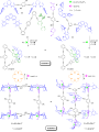
Figure 10: Communication between the nanoswitch 21 and the supramolecular assemblies [Cu4(22)2(24)2]4+ or [Cu6(...

Figure 11: (a) The chemical structures and cartoon representations of the switch 25, the decks 26 and 27, and ...

Figure 12: Double self-sorting leads to a catalytic machinery in SelfSORT-II, in which the 46 kHz-nanorotor ac...

Figure 13: ON/OFF control of a networked catalytic catch–release system.

Figure 14: A multicomponent information system for the reversible reconfiguration of switchable dual catalysis....

Figure 15: a) The chemically fueled cascaded ion translocation, monitored by distinct emission colors. b) Work...
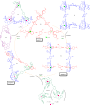
Figure 16: Cyclic metallosupramolecular transformations.

Figure 17: Fully reversible multiple-state rearrangement of metallosupramolecular architectures depending upon...

Figure 18: The selective encapsulation and sequential release of guests in a self-sorted mixture of three tetr...

Figure 19: Two catalytic reactions are alternately controlled by a toggle nanoswitch.
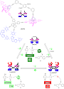
Figure 20: A biped walking along a tetrahedral track and unfolding its catalytic action. Adapted with permissi...
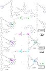
Figure 21: A three state supramolecular AND logic gate.

Figure 22: Four-component nanorotor and its catalytic activity. Adapted with permission from (Biswas, P. K.; S...
Palladium nanoparticles supported on chitin-based nanomaterials as heterogeneous catalysts for the Heck coupling reaction
- Tony Jin,
- Malickah Hicks,
- Davis Kurdyla,
- Sabahudin Hrapovic,
- Edmond Lam and
- Audrey Moores
Beilstein J. Org. Chem. 2020, 16, 2477–2483, doi:10.3762/bjoc.16.201
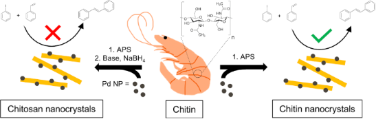
- deposit Pd NPs directly onto both ChNCs and ChsNCs, and the as-made heterogeneous catalysts were tested with the Heck coupling reaction as a model for catalytic activity. Findings The fabrication of ChNC and ChsNCs was conducted using a procedure previously reported by our group (Lam) (see Supporting
- system has higher catalytic activity in more benign conditions, with the Pd NP on SiO2 system yielding 92% stilbene product at 110 °C and using dimethylformamide as the solvent [23]. Other examples using carbon-based supports such as carbon spheres [24] and graphene oxide [25] also have formidable yields

Graphical Abstract

Scheme 1: Pathway for the formation of ChNC and subsequently ChsNCs from bulk chitin.

Figure 1: TEM micrographs of (a) ChNCs and (b) ChsNCs. Both samples were stained and prepared on glow-dischar...

Scheme 2: Catalyst fabrication method for the deposition of Pd NPs onto chitin (PdNP@ChNC) and chitosan (PdNP...

Figure 2: TEM micrographs of (a) PdNP@ChNCs and (b) PdNP@ChsNCs. The samples were placed on glow discharged T...

Figure 3: High-resolution X-ray photoelectron spectroscopy of the Pd 3d region of (a) PdNP@ChNC and (b) PdNP@...
Hierarchically assembled helicates as reaction platform – from stoichiometric Diels–Alder reactions to enamine catalysis
- David Van Craen,
- Jenny Begall,
- Johannes Großkurth,
- Leonard Himmel,
- Oliver Linnenberg,
- Elisabeth Isaak and
- Markus Albrecht
Beilstein J. Org. Chem. 2020, 16, 2338–2345, doi:10.3762/bjoc.16.195
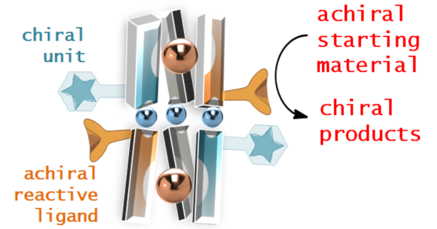
- residues were introduced instead of the diene ligands. Again helicates with a statistical distribution of chiral ligands and of the new amine ligands in the complex were investigated as catalysts. The ligands with potential catalytic activity were synthesized in a three-step approach (Scheme 4). Initially
- equivalent of 13-H2 and 5 equivalents of 2-H2, 4-H2, and 5-H2. The catalytic activity of the amine ligands was tested first by using the uncoordinated ligand 13a-H2 substituted with a N-methylethylamine moiety. The reaction was performed in DMSO-d6 due to solubility limitations of the ligand. Fast and easy
- the supposed reason for this observation. Thus, the amine ligand 13b-H2 seemed to be an appropriate component to make helicates from ligand mixtures which possess catalytic activity. Exchange of the chiral ligand 2 by other chiral ones resulted in the corresponding complexes Li4[(13b)1(4)5Ti2] and Li4

Graphical Abstract

Scheme 1: Formation of hierarchically assembled lithium-bridged titanium(IV) helicates as well as the ligands...

Scheme 2: Previously reported on/off switch for “remote-controlled” [23-31] stereoselectivity of a Diels–Alder react...

Scheme 3: Elucidating the pathway of the stereoinduction of the Diels–Alder reaction. Ten equivalents of chir...
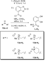
Scheme 4: Synthesis of the ligands with secondary amine-containing substituents.
Synthetic approaches to bowl-shaped π-conjugated sumanene and its congeners
- Shakeel Alvi and
- Rashid Ali
Beilstein J. Org. Chem. 2020, 16, 2212–2259, doi:10.3762/bjoc.16.186
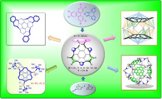
- colorless crystals of 128. Along similar lines the crystals of 127 were achieved by following the same procedure. On the other hand, the groups of Amaya and Hirao have reported the synthesis of sumanenyl mono- and trihafnocene complexes 129 and 130, respectively, along with the catalytic activity of 129 for
- subjected 2 with an excess of t-BuLi and then quenched it with Cp*HfCl3 as displayed in Scheme 34. Furthermore, they revealed for the first time the catalytic activity of sumanene metallocene for the hydroethylation reaction of unactivated allylbenzene by treating it with AlEt3 at room temperature to

Graphical Abstract
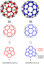
Figure 1: Representation of corannulene (1) and sumanene (2), the subunits of fullerene (C60).

Scheme 1: Mehta’s unsuccessful effort for the synthesis of sumanene scaffold 2.

Scheme 2: First synthesis of sumanene 2 by Sakurai et al. from norbornadiene 10.

Scheme 3: Synthesis of trimethylsumanene 28 from easily accessible norbornadiene (10).

Scheme 4: Generation of anions 29–31 and the preparation of tris(trimethylsilyl)sumanene 32.

Scheme 5: Synthesis of tri- and hexa-substituted sumanene derivatives.

Scheme 6: Synthesis of bowl-shaped π-extended sumanene derivatives 37a–f.

Scheme 7: Synthesis of monooxasumanene 38, trioxosumanene 40 along with imination of them.

Scheme 8: Synthesis of trimethylsumanenetrione 46 and exo-functionalized products 45a,b.

Scheme 9: Synthesis of bisumanenylidene 47 and sumanene dimer 48 from 2.

Scheme 10: The mono-substitution of 2 to generate diverse mono-sumanene derivatives 49a–d.

Scheme 11: Synthesis of sumanene building block 53 useful for further extension.

Scheme 12: Synthesis of hexafluorosumanene derivative 55 by Sakurai and co-workers.

Scheme 13: Preparation of sumanene-based carbene 60 and its reaction with cyclohexane.

Scheme 14: Barton–Kellogg reaction for the synthesis of sterically hindered alkenes.

Scheme 15: Synthesis of hydroxysumanene 68 by employing Baeyer–Villiger oxidation.

Scheme 16: Synthesis of sumanene derivatives having functionality at an internal carbon.

Scheme 17: Mechanism for nucleophilic substitution reaction at the internal carbon.

Scheme 18: Synthesis of diverse monosubstituted sumanene derivatives.
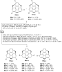
Scheme 19: Synthesis of di- and trisubstituted sumanene derivatives from sumanene (2).

Scheme 20: Preparation of monochlorosumanene 88 and hydrogenation of sumanene (2).

Scheme 21: The dimer 90 and bissumanenyl 92 achieved from halosumannes.

Scheme 22: Pyrenylsumanene 93 involving the Suzuki-coupling as a key transformation.
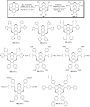
Scheme 23: Synthesis of various hexaarylsumanene derivatives using the Suzuki-coupling reaction.

Scheme 24: Synthesis of hexasubstituted sumanene derivatives 96 and 97.

Scheme 25: Synthesis of thioalkylsumanenes via an aromatic nucleophilic substitution reaction.

Scheme 26: Synthesis of tris(ethoxycarbonylethenyl)sumanene derivative 108.
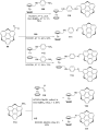
Scheme 27: Synthesis of ferrocenyl-based sumanene derivatives.

Scheme 28: Synthesis of sumanenylferrocene architectures 118 and 119 via Negishi coupling.

Scheme 29: Diosmylation and the synthesis of phenylboronate ester 121 of sumanene.

Scheme 30: Synthesis of the iron-complex of sumanene.

Scheme 31: Synthesis of tri- and mononuclear sumanenyl zirconocene complexes.

Scheme 32: Synthesis of [CpRu(η6-sumanene)]PF6.

Scheme 33: Preparation of sumanene-based porous coordination networks 127 (spherical tetramer units) and 128 (...

Scheme 34: Synthesis of sumanenylhafnocene complexes 129 and 130.

Scheme 35: Synthesis of 134 and 135 along with PdII coordination complex 136.

Scheme 36: Synthesis of alkali metals sumanene complex K7(C21H102−)2(C21H93−)·8THF (137) containing di- and tr...

Scheme 37: The encapsulation of a Cs+ ion between two sumanenyl anions.

Scheme 38: Synthesis of monothiasumanene 140 and dithiasumanene 141 from 139.

Scheme 39: Synthesis of trithiasumanene 151 by Otsubo and his co-workers.

Scheme 40: Synthesis of trithiasumanene derivatives 155 and 156.

Scheme 41: Synthetic route towards hexathiolated trithiasumanenes 158.

Scheme 42: Synthesis of triselenasumanene 160 by Shao and teammates.

Scheme 43: Synthesis of tritellurasumanene derivatives from triphenylene skeletons.
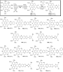
Scheme 44: Synthesis of pyrazine-fused sumanene architectures through condensation reaction.

Scheme 45: Treatment of the trichalcogenasumanenes with diverse oxidative reagents.

Scheme 46: Ring-opening reaction with H2O2 and oxone of heterasumanenes 178 and 179.

Scheme 47: Synthesis of polycyclic compounds from sumanene derivatives.

Scheme 48: Synthesis of diimide-based heterocycles reported by Shao’s and co-workers.

Scheme 49: Synthesis of pristine trichalcogenasumanenes, 151, 205, and 206.

Scheme 50: Synthesis of trichalcogenasumanenes via hexaiodotriphenylene precursor 208.

Scheme 51: Synthesis of trisilasumanenes 214 and 215.

Scheme 52: Synthesis of trisilasumanene derivatives 218 and 219.

Scheme 53: Synthesis of novel trigermasumanene derivative 223.

Scheme 54: An attempt towards the synthesis of tristannasumanene derivative 228.

Scheme 55: Synthesis of triphosphasumanene trisulfide 232 from commercially available 229.

Scheme 56: The doping of sumanene derivatives with chalcogens (S, Se, Te) and phosphorus.

Scheme 57: Synthesis of heterasumanene containing three different heteroatoms.

Scheme 58: Synthesis of trichalcogenasumanene derivatives 240 and 179.

Scheme 59: Preparation of trichalcogenasumanenes 245 and 248.

Scheme 60: Design and synthesis of trichalcogenasumanene derivatives 252 and 178.

Scheme 61: Synthesis of spirosumanenes 264–269 and non-spiroheterasumanenes 258–263.

Scheme 62: Synthesis of sumanene-type hetero polycyclic compounds.

Scheme 63: Synthesis of triazasumanenes 288 and its sulfone congener 287.

Scheme 64: Synthesis of C3-symmetric chiral triaryltriazasumanenes via cross-coupling reaction.

Scheme 65: Synthesis of mononaphthosumanene 293 using Suzuki coupling as a key step.

Scheme 66: Synthesis of di- and trinaphthosumanene derivatives 302–304.

Scheme 67: Synthesis of hemifullerene skeletons by Hirao’s group.

Scheme 68: Design and construction of C70 fragment from a C60 sumanene fragment.
Azo-dimethylaminopyridine-functionalized Ni(II)-porphyrin as a photoswitchable nucleophilic catalyst
- Jannis Ludwig,
- Julian Helberg,
- Hendrik Zipse and
- Rainer Herges
Beilstein J. Org. Chem. 2020, 16, 2119–2126, doi:10.3762/bjoc.16.179
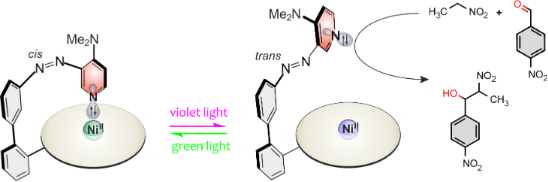
- switch the catalytic activity of the dimethylaminopyridine (DMAP) unit. DMAP is a known catalyst in the nitroaldol (Henry) reaction. Upon coordination to the Ni2+ ion, the basicity of the pyridine lone pair is attenuated and hence the catalytic activity is reduced. Decoordination restores the catalytic
- -epoxypropane to propylene carbonate using an aluminum porphyrin and a photoresponsive ligand. The catalytic activity of the metal porphyrin depended on the axial coordination of an azostilbene and coordination of the latter ligand was controlled by photoisomerization of the stilbene unit [9]. Hecht et al
- thermal relaxation of the coordinated cis state is insignificant for our catalytic studies. Experiments using porphyrin 1 as a catalyst The Henry reaction (Scheme 2) was chosen as a model reaction to investigate the catalytic activity of porphyrin 1 in the two different switching states because the rate

Graphical Abstract

Figure 1: Basicity and nucleophilicity switching of the 4-(N,N-dimethylamino)pyridine “record player” molecul...

Scheme 1: Synthesis of 4-N,N-dimethylamino record player molecule 1 by Suzuki reaction between Ni-porphyrin p...

Figure 2: Composition of the different states of porphyrin 1 (1 mM) in the PSS at 530 nm and 435 nm, determin...

Figure 3: a) UV–vis cuvette with a solution of porphyrin 1 (13.1 µM in THF) and the corresponding UV–vis spec...

Scheme 2: General scheme of the nitroaldol (Henry) reaction that was used to investigate photoswitchable cata...

Scheme 3: DMAP (2), azopyridine trans-4, record player trans- and cis-1 and Ni-porphyrin 8 were used in kinet...

Figure 4: Conversion of 4-nitrobenzaldehyde (6) in the Henry reaction with nitroethane (5) as a function of t...
Efficient [(NHC)Au(NTf2)]-catalyzed hydrohydrazidation of terminal and internal alkynes
- Maximillian Heidrich and
- Herbert Plenio
Beilstein J. Org. Chem. 2020, 16, 2080–2086, doi:10.3762/bjoc.16.175
- in hydrohydrazidation reactions than the previously reported [(Ph3P)Au(NTf2)] [42]. Solvent screening: Among the solvents tested in the previous study by Rassadin, Kukushkin et al., chlorobenzene was found to be the best solvent concerning the catalytic activity [42]. However, according to the CHEM21

Graphical Abstract

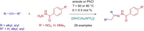
Scheme 1: Simplified mechanism of the hydrohydrazidation (NuH= ArCONHNH2) of alkynes.

Scheme 2: [(NHC)Au(NTf2)] complexes tested in hydrohydrazidation reactions of phenylacetylene.

Scheme 3: Hydrohydrazidation of terminal alkynes in chlorobenzene and anisole using complex 1 (first line sol...

Scheme 4: Hydrohydrazidation of internal alkynes in chlorobenzene and anisole using complex 1. Reaction tempe...
Synergy between supported ionic liquid-like phases and immobilized palladium N-heterocyclic carbene–phosphine complexes for the Negishi reaction under flow conditions
- Edgar Peris,
- Raúl Porcar,
- María Macia,
- Jesús Alcázar,
- Eduardo García-Verdugo and
- Santiago V. Luis
Beilstein J. Org. Chem. 2020, 16, 1924–1935, doi:10.3762/bjoc.16.159
- PdII. In this way, a “cocktail” of catalytic species, including molecular complexes, clusters and nanoparticles may be responsible for the catalytic activity [15]. In a continuous system, this can be accompanied by a significant leaching of the catalytic metal. In order to avoid a loss of activity by
- kinetic plots for this model reaction are represented in Figure 1. The NHC–Pd catalyst 4a showed a rather reduced activity (less than 10% after two hours), while the catalyst bearing isopropyl moieties at the aromatic ring (4b) displayed a significant increase in the catalytic activity, reaching 67% yield
- enhanced precatalyst preparation, stabilization and initiation, PEPPSI) [23][24]. In addition to pyridine ligands, other compounds with coordinating atoms such as C, N or P have been reported to tune the catalytic activity of the NHC–Pd complexes [25][26][27][28]. Thus, a ligand containing P as the

Graphical Abstract

Scheme 1: Synthesis of NHC-supported catalysts.

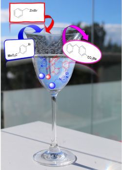
Scheme 2: Negishi benchmark reaction.
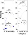
Figure 1: Negishi reaction catalyzed by immobilized NHC–Pd complexes. Conditions: methyl 4-bromobenzoate (0.2...

Scheme 3: Synthesis of immobilized NHC–Pd–RuPhos.

Figure 2: Negishi model reaction between 5 and 6 under flow conditions catalyzed by 4b. V = 0.535 mL, 363 mg ...

Figure 3: Negishi model reaction under flow conditions catalyzed by 8a. V = 2.9 mL, 1.25 g of catalyst, resid...
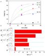
Figure 4: Negishi reaction between 5 and 6 catalyzed by 8a in the presence of SILLPs. a) Yield (%) vs time fo...

Figure 5: TEM images of the polymers after the Negishi reaction between 5 and 6. a) 8a, bar scale 20 nm, PdNP...

Scheme 4: Pd species immobilized onto SILLPs. i) 1 g SILLP 10, 100 mg PdCl2 in milli-Q® water (100 mL 1% HCl,...

Figure 6: Negishi reaction between 5 and 6 catalyzed by 11. 1 equiv methyl 4-bromobenzoate (6, 0.25 mmol), 2 ...

Figure 7: Negishi reaction between 5 and 6 under flow conditions catalyzed by 8a in the presence of a scaveng...

Figure 8: Effect of the structure of the SILLP scavenger for the Negishi reaction between 5 and 6 under flow ...

Figure 9: TEM images of the polymer after the Negishi reaction between 5 and 6 under flow conditions. a) 8a + ...
Natural dolomitic limestone-catalyzed synthesis of benzimidazoles, dihydropyrimidinones, and highly substituted pyridines under ultrasound irradiation
- Kumar Godugu,
- Venkata Divya Sri Yadala,
- Mohammad Khaja Mohinuddin Pinjari,
- Trivikram Reddy Gundala,
- Lakshmi Reddy Sanapareddy and
- Chinna Gangi Reddy Nallagondu
Beilstein J. Org. Chem. 2020, 16, 1881–1900, doi:10.3762/bjoc.16.156
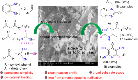
- , the elemental composition of the NDL catalyst was determined by EDAX analysis (Figure 6). The catalytic activity of the NDL for the synthesis of the 1,2-disubstituted benzimidazoles 3, the dihydropyrimidinones/-thiones 7, and the 2-amino-4-(hetero)aryl-3,5-dicarbonitrile-6-sulfanylpyridines 11 was
- investigated, along with other, commercially available catalysts. NDL-catalyzed synthesis of 1,2-disubtituted benzimidazoles 3 To check the catalytic activity of the NDL, initially, o-phenylenediamine (1) and benzaldehyde (2a) were chosen as model substrates to optimize the reaction conditions for the
- by comparison of the melting point and spectroscopic data with those reported. NDL-catalyzed synthesis of dihydropyrimidinones/-thiones 7 The results encouraged us to further investigate the catalytic activity of the NDL in the Biginelli reaction. To check the feasibility, a control experiment was

Graphical Abstract

Figure 1: The benzimidazoles I–IV, dihydropyrimidinones/-thiones V–VIII, and 2-amino-4-aryl-3,5-dicarbonitril...

Scheme 1: NDL-catalyzed synthesis of i) 1,2-disubstituted benzimidazoles 3, ii) dihydropyrimidinones/-thiones ...

Figure 2: XRD pattern of the NDL catalyst.

Figure 3: FTIR spectrum of the NDL catalyst.

Figure 4: Raman spectrum of the NDL catalyst.

Figure 5: SEM images of the NDL catalyst.

Figure 6: EDAX analysis of the NDL catalyst.

Scheme 2: Unexpected formation of the bisimine I, 3h, from o-phenylenediamine (1) and salicylaldehyde (2h).

Figure 7: 1H NMR spectrum of 2,2'-((1E,1'E)-(1,2-phenylenebis(azanylylidene))bis (methanylylidene))diphenol (...
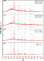
Figure 8: XRD pattern of a) the fresh NDL catalyst; b) the recovered NDL catalyst after the 7th cycle of the ...
One-pot synthesis of isosorbide from cellulose or lignocellulosic biomass: a challenge?
- Isaline Bonnin,
- Raphaël Mereau,
- Thierry Tassaing and
- Karine De Oliveira Vigier
Beilstein J. Org. Chem. 2020, 16, 1713–1721, doi:10.3762/bjoc.16.143
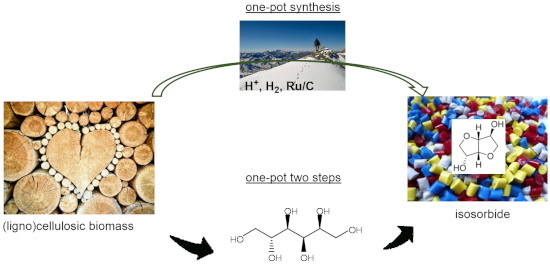
- increased production of insoluble byproducts. The productivity of isosorbide can reach 40.2 g·L−1·h−1with a purity of 73%. The recycling of the metal-supported catalyst (Ru/C) was studied and a high catalytic activity decrease was observed after the first run, showing that the catalyst was not recyclable

Graphical Abstract

Scheme 1: Conversion of cellulose to isosorbide.

Scheme 2: Combination of mineral acids or heteropolyacids and a supported metal catalyst to produce isosorbid...

Scheme 3: Conversion of sorbitol to isosorbide via the formation of sorbitans.

Scheme 4: Conversion of cellulose to isosorbide in the presence of heteropolyacids and metal-supported cataly...

Scheme 5: Summary of the results obtained in one-pot one step processes [21-25].

Scheme 6: Conversion of (ligno)cellulose to isosorbide in the presence of Amberlyt 70 and a Ru/C catalyst [26,27].

Scheme 7: Use of Ru-supported on mesoporous nobium phosphate (mNbPO) for the synthesis of isosorbide from cel...
Activated carbon as catalyst support: precursors, preparation, modification and characterization
- Melanie Iwanow,
- Tobias Gärtner,
- Volker Sieber and
- Burkhard König
Beilstein J. Org. Chem. 2020, 16, 1188–1202, doi:10.3762/bjoc.16.104
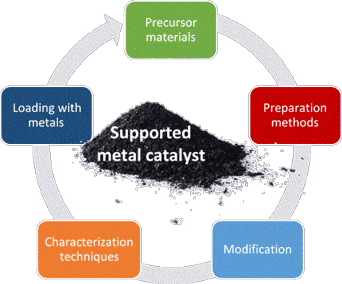

Graphical Abstract

Figure 1: Experimental setup of ultrasonic spray pyrolysis. Reprinted with permission from [95], copyright 2006 T...

Figure 2: Overview of nitrogen-containing functional groups on the surface of activated carbons. Scheme was d...
A smart deoxyribozyme-based fluorescent sensor for in vitro detection of androgen receptor mRNA
- Ekaterina A. Bryushkova,
- Erik R. Gandalipov and
- Julia V. Nuzhina
Beilstein J. Org. Chem. 2020, 16, 1135–1141, doi:10.3762/bjoc.16.100
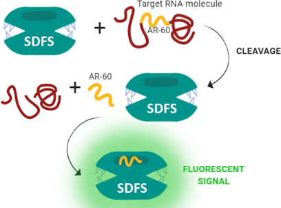
- 2D, lane 6). As follows from Figure 2D (lanes 6 and 7), the presence of malachite green dye did not affect the catalytic activity of SDFS. Selectivity of SDFS cleavage activity in relation to 60-AR_RNA was tested with two random RNA sequences (Supporting Information File 1, Table S2, 62-RNA and 46

Graphical Abstract
Figure 1: SDFS main components and its work model. A) Schematic representation of the SDFS structure. Dotted ...

Figure 2: The SDFS functional activity. A–C) Emission spectra of the assembled SDFS (green line), T1–T5 chain...

Figure 3: Emission spectra of SDFS activity on total cellular RNA. The green line represents a spectrum of SD...
The charge-assisted hydrogen-bonded organic framework (CAHOF) self-assembled from the conjugated acid of tetrakis(4-aminophenyl)methane and 2,6-naphthalenedisulfonate as a new class of recyclable Brønsted acid catalysts
- Svetlana A. Kuznetsova,
- Alexander S. Gak,
- Yulia V. Nelyubina,
- Vladimir A. Larionov,
- Han Li,
- Michael North,
- Vladimir P. Zhereb,
- Alexander F. Smol'yakov,
- Artem O. Dmitrienko,
- Michael G. Medvedev,
- Igor S. Gerasimov,
- Ashot S. Saghyan and
- Yuri N. Belokon
Beilstein J. Org. Chem. 2020, 16, 1124–1134, doi:10.3762/bjoc.16.99
- volume of 0.00093 cm3⋅g−1, a macropore volume of 0.00168 cm3⋅g−1, and a total pore volume of 0.00336 cm3⋅g−1. The porosimetry data could not be directly relevant to the catalytic activity of the composite as the framework as the porosimetry sample needed to be thoroughly degassed prior to the analysis
- styrene oxide (2) with methanol. Within 1 hour at room temperature, the alcohol 3 was obtained in a quantitative yield and as a single regioisomer (Table 1, run 2). The CAHOF F-1 was robust and retained the catalytic activity after being recovered from the reaction mixture five times (Table 1, run 3). In

Graphical Abstract

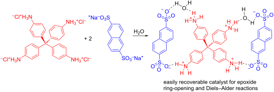
Scheme 1: The synthesis of F-1.

Figure 1: View of the crystal structure of F-1 (F-1a phase), with representation of atoms by thermal ellipsoi...

Figure 2: View of the crystal structure of F-1 (F-1a’ phase), with representation of the atoms via thermal el...

Figure 3: SEM image of F-1.

Figure 4: SEM image of F-1 with an F-1a phase.

Figure 5: TGA-DSC analysis of a sample of F-1. The TGA plot is shown in green, the DSC curve is shown in blue...
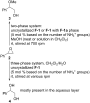
Scheme 2: Uncrystallized F-1 or F-1 with an F-1a phase promoted the two- and three-phase reactions of styrene...

Scheme 3: CAHOF F-1-promoted reactions of cyclohexene oxide (5) with alcohols and water.

Scheme 4: F-1-promoted Diels–Alder reaction.
Recent advances in Cu-catalyzed C(sp3)–Si and C(sp3)–B bond formation
- Balaram S. Takale,
- Ruchita R. Thakore,
- Elham Etemadi-Davan and
- Bruce H. Lipshutz
Beilstein J. Org. Chem. 2020, 16, 691–737, doi:10.3762/bjoc.16.67
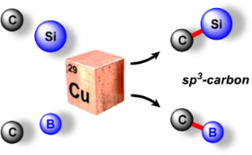
- , provided an opportunity for recycling and reuse. This catalyst, therefore, was isolated using simple centrifugation and reused in a second reaction leading to no appreciable loss in catalytic activity en route to product 218. It was also utilized not only for unsaturated ketones but also to deliver the
- coordination of (t-Bu)3P to CuCl is far greater than that with the diboron species, which results in an enhancement of the catalytic activity (Scheme 65) [128]. The one-pot borylation/protodeboronation of α,β-unsaturated ketones 405 in the presence of CuBr, B2pin2 and H2O as the hydrogen source was developed

Graphical Abstract

Scheme 1: Pharmaceuticals possessing a silicon or boron atom.

Scheme 2: The first Cu-catalyzed C(sp3)–Si bond formation.

Scheme 3: Conversion of benzylic phosphate 6 to the corresponding silane.

Scheme 4: Conversion of alkyl triflates to alkylsilanes.

Scheme 5: Conversion of secondary alkyl triflates to alkylsilanes.

Scheme 6: Conversion of alkyl iodides to alkylsilanes.

Scheme 7: Trapping of intermediate radical through cascade reaction.

Scheme 8: Radical pathway for conversion of alkyl iodides to alkylsilanes.

Scheme 9: Conversion of alkyl ester of N-hydroxyphthalimide to alkylsilanes.

Scheme 10: Conversion of gem-dibromides to bis-silylalkanes.

Scheme 11: Conversion of imines to α-silylated amines (A) and the reaction pathway (B).

Scheme 12: Conversion of N-tosylimines to α-silylated amines.

Scheme 13: Screening of diamine ligands.

Scheme 14: Conversion of N-tert-butylsulfonylimines to α-silylated amines.

Scheme 15: Conversion of aldimines to nonracemic α-silylated amines.

Scheme 16: Conversion of N-tosylimines to α-silylated amines.

Scheme 17: Reaction pathway [A] and conversion of aldehydes to α-silylated alcohols [B].

Scheme 18: Conversion of aldehydes to benzhydryl silyl ethers.

Scheme 19: Conversion of ketones to 1,2-diols (A) and conversion of imines to 1,2-amino alcohols (B).

Scheme 20: Ligand screening (A) and conversion of aldehydes to α-silylated alcohols (B).

Scheme 21: Conversion of aldehydes to α-silylated alcohols.

Scheme 22: 1,4-Additions to α,β-unsaturated ketones.

Scheme 23: 1,4-Additions to unsaturated ketones to give β-silylated derivatives.

Scheme 24: Additions onto α,β-unsaturated lactones to give β-silylated lactones.

Scheme 25: Conversion of α,β-unsaturated to β-silylated lactams.

Scheme 26: Conversion of N-arylacrylamides to silylated oxindoles.

Scheme 27: Conversion of α,β-unsaturated carbonyl compounds to silylated tert-butylperoxides.

Scheme 28: Catalytic cycle for Cu(I) catalyzed α,β-unsaturated compounds.

Scheme 29: Conversion of p-quinone methides to benzylic silanes.

Scheme 30: Conversion of α,β-unsaturated ketimines to regio- and stereocontrolled allylic silanes.

Scheme 31: Conversion of α,β-unsaturated ketimines to enantioenriched allylic silanes.

Scheme 32: Regioselective conversion of dienedioates to allylic silanes.

Scheme 33: Conversion of alkenyl-substituted azaarenes to β-silylated adducts.

Scheme 34: Conversion of conjugated benzoxazoles to enantioenriched β-silylated adducts.

Scheme 35: Conversion of α,β-unsaturated carbonyl indoles to α-silylated N-alkylated indoles.

Scheme 36: Conversion of β-amidoacrylates to α-aminosilanes.

Scheme 37: Conversion of α,β-unsaturated ketones to enantioenriched β-silylated ketones, nitriles, and nitro d...

Scheme 38: Regio-divergent silacarboxylation of allenes.

Scheme 39: Silylation of diazocarbonyl compounds, (A) asymmetric and (B) racemic.

Scheme 40: Enantioselective hydrosilylation of alkenes.

Scheme 41: Conversion of 3-acylindoles to indolino-silanes.

Scheme 42: Proposed mechanism for the silylation of 3-acylindoles.

Scheme 43: Silyation of N-chlorosulfonamides.

Scheme 44: Conversion of acyl silanes to α-silyl alcohols.

Scheme 45: Conversion of N-tosylaziridines to β-silylated N-tosylamines.

Scheme 46: Conversion of N-tosylaziridines to silylated N-tosylamines.

Scheme 47: Conversion of 3,3-disubstituted cyclopropenes to silylated cyclopropanes.

Scheme 48: Conversion of conjugated enynes to 1,3-bis(silyl)propenes.

Scheme 49: Proposed sequence for the Cu-catalyzed borylation of substituted alkenes.

Scheme 50: Cu-catalyzed synthesis of nonracemic allylic boronates.

Scheme 51: Cu–NHC catalyzed synthesis of α-substituted allylboronates.
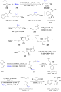
Scheme 52: Synthesis of α-chiral (γ-alkoxyallyl)boronates.

Scheme 53: Cu-mediated formation of nonracemic cis- or trans- 2-substituted cyclopropylboronates.

Scheme 54: Cu-catalyzed synthesis of γ,γ-gem-difluoroallylboronates.

Scheme 55: Cu-catalyzed hydrofunctionalization of internal alkenes and vinylarenes.

Scheme 56: Cu-catalyzed Markovnikov and anti-Markovnikov borylation of alkenes.

Scheme 57: Cu-catalyzed borylation/ortho-cyanation/Cope rearrangement.
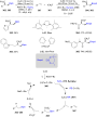
Scheme 58: Borylfluoromethylation of alkenes.

Scheme 59: Cu-catalyzed synthesis of tertiary nonracemic alcohols.

Scheme 60: Synthesis of densely functionalized and synthetically versatile 1,2- or 4,3-borocyanated 1,3-butadi...

Scheme 61: Cu-catalyzed trifunctionalization of allenes.

Scheme 62: Cu-catalyzed selective arylborylation of arenes.

Scheme 63: Asymmetric borylative coupling between styrenes and imines.

Scheme 64: Regio-divergent aminoboration of unactivated terminal alkenes.

Scheme 65: Cu-catalyzed 1,4-borylation of α,β-unsaturated ketones.

Scheme 66: Cu-catalyzed protodeboronation of α,β-unsaturated ketones.

Scheme 67: Cu-catalyzed β-borylation of α,β-unsaturated imines.

Scheme 68: Cu-catalyzed synthesis of β-trifluoroborato carbonyl compounds.

Scheme 69: Asymmetric 1,4-borylation of α,β-unsaturated carbonyl compounds.

Scheme 70: Cu-catalyzed ACB and ACA reactions of α,β-unsaturated 2-acyl-N-methylimidazoles.

Scheme 71: Cu-catalyzed diborylation of aldehydes.

Scheme 72: Umpolung pathway for chiral, nonracemic tertiary alcohol synthesis (top) and proposed mechanism for...

Scheme 73: Cu-catalyzed synthesis of α-hydroxyboronates.

Scheme 74: Cu-catalyzed borylation of ketones.

Scheme 75: Cu-catalyzed borylation of unactivated alkyl halides.

Scheme 76: Cu-catalyzed borylation of allylic difluorides.

Scheme 77: Cu-catalyzed borylation of cyclic and acyclic alkyl halides.

Scheme 78: Cu-catalyzed borylation of unactivated alkyl chlorides and bromides.

Scheme 79: Cu-catalyzed decarboxylative borylation of carboxylic acids.
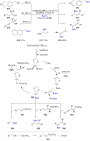
Scheme 80: Cu-catalyzed borylation of benzylic, allylic, and propargylic alcohols.
Rhodium-catalyzed reductive carbonylation of aryl iodides to arylaldehydes with syngas
- Zhenghui Liu,
- Peng Wang,
- Zhenzhong Yan,
- Suqing Chen,
- Dongkun Yu,
- Xinhui Zhao and
- Tiancheng Mu
Beilstein J. Org. Chem. 2020, 16, 645–656, doi:10.3762/bjoc.16.61
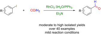
- . In this work, we established a catalytic system composed of RhCl3·3H2O and PPh3, which allows the reductive carbonylation of aryl iodides using CO and H2 in the presence of Et3N as the base at 90 °C. In addition, the reported catalytic system demonstrates high catalytic activity affording the

Graphical Abstract

Figure 1: Rhodium-catalyzed reductive carbonylation of iodobenzene with CO and H2 to afford benzaldehyde. a) ...

Scheme 1: Scaled-up experiment of the reductive carbonylation of iodobenzene to benzaldehyde under the optimi...

Scheme 2: Catalytic species participating in the catalytic process.
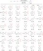
Scheme 3: Substrate scope for the Rh-catalyzed reductive carbonylation of aryl iodides using CO and H2. React...

Scheme 4: Isotope-labeling experiments.

Scheme 5: Proposed reaction mechanism for the Rh-catalyzed reductive carbonylation of aryl iodides using CO a...
Asymmetric synthesis of CF2-functionalized aziridines by combined strong Brønsted acid catalysis
- Xing-Fa Tan,
- Fa-Guang Zhang and
- Jun-An Ma
Beilstein J. Org. Chem. 2020, 16, 638–644, doi:10.3762/bjoc.16.60
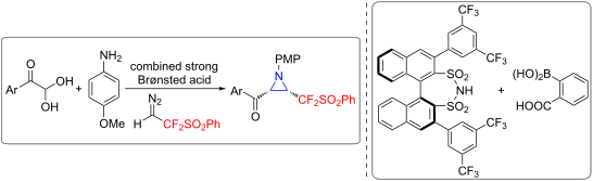
- examination on various arylboronic acids, solvent, temperature, and catalyst loadings resulted in no obvious improvement (Table 1, entries 9–15). Among them, the highest yield of 4a was observed (81%, Table 1, entry 12), albeit with slightly reduced ee value. This enhancement in catalytic activity could be

Graphical Abstract

Scheme 1: Preparation of chiral aziridines from fluorinated diazo reagents.

Scheme 2: Substrate scope of chiral CF2-substituted aziridines from PhSO2CF2CHN2. General reaction conditions...

Scheme 3: Scale-up experiment to 4a and further synthetic transformations.