

Search results
Search for "tryptophan" in Full Text gives 114 result(s) in Beilstein Journal of Organic Chemistry.
Steroid diversification by multicomponent reactions
- Leslie Reguera,
- Cecilia I. Attorresi,
- Javier A. Ramírez and
- Daniel G. Rivera
Beilstein J. Org. Chem. 2019, 15, 1236–1256, doi:10.3762/bjoc.15.121
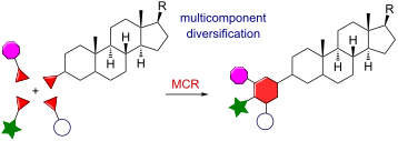
- their subsequent utilization in the Ugi-4CR with monoprotected amino acids (used either as amino or carboxylic acid components) and formaldehyde as fixed oxo component. Amazingly, the Ugi-4CR of steroidal triisocyanide 26 with three equivalents of Boc-tryptophan allowed the formation of twelve covalent

Graphical Abstract

Figure 1: Structures of natural steroids of A) animal and B) plant origin.

Scheme 1: Synthesis of a steroidal β-lactam by Ugi reaction of a cholanic aldehyde [14].

Scheme 2: Synthetic route to steroidal 2,5-diketopiperazines based on a diastereoselective Ugi-4CR with an an...

Scheme 3: Multicomponent synthesis of a heterocycle–steroid hybrid using a ketosteroid as carbonyl component [18]....

Scheme 4: Synthesis of peptidomimetic–steroid hybrids using the Ugi-4CR with spirostanic amines and carboxyli...

Scheme 5: Synthesis of azasteroids using the Ugi-4CR with androstanic and pregnanic carboxylic acids [22].

Figure 2: Ugi-4CR-derived library of androstanic azasteroids with diverse substitution patterns at the phenyl...

Scheme 6: Synthesis of 4-azacholestanes by an intramolecular Ugi-4C-3R [26].

Scheme 7: Synthesis of amino acid–steroid hybrid by multiple Ugi-4CR using steroidal isocyanides [29].

Scheme 8: Synthesis of ecdysteroid derivatives by Ugi-4CR using a steroidal isocyanide [30].

Scheme 9: Stereoselective multicomponent synthesis of a steroid–tetrahydropyridine hybrid using a chiral bifu...

Scheme 10: Pd(II)-catalyzed three-component reaction with an alkynyl seco-cholestane [34].

Scheme 11: Multicomponent synthesis of steroid–thiazole hybrids from a steroidal ketone [36].

Scheme 12: Synthesis of cholanic pseudo-peptide derivatives by novel MCRs based on the reactivity of ynamide [37,38].

Scheme 13: Synthesis of steroid-fused pyrimidines and pyrimidones using the Biginelli-3CR [39,42,43].

Scheme 14: Synthesis of steroidal pyridopyrimidines by a reaction sequence comprising a 4CR followed by a post...

Scheme 15: Synthesis of steroid-fused pyrimidines by MCR of 2-hydroxymethylene-3-ketosteroids [46].

Scheme 16: Synthesis of steroid-fused naphthoquinolines by the Kozlov–Wang MCR using ketosteroids [50,51].

Scheme 17: Conjugation of steroids to carbohydrates and peptides by the Ugi-4CR [62,63].

Scheme 18: Solid-phase multicomponent conjugation of peptides to steroids by the Ugi-4CR [64].

Scheme 19: Solid-phase multicomponent conjugation of peptides to steroids by the Petasis-3CR [68].
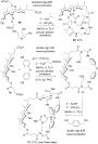
Scheme 20: Synthesis of steroidal macrobicycles (cages) by multiple multicomponent macrocyclizations based on ...

Scheme 21: One-pot synthesis of steroidal cages by double Ugi-4CR-based macrocyclizations [76].
Synthesis of a novel category of pseudo-peptides using an Ugi three-component reaction of levulinic acid as bifunctional substrate, amines, and amino acid-based isocyanides
- Maryam Khalesi,
- Azim Ziyaei Halimehjani and
- Jürgen Martens
Beilstein J. Org. Chem. 2019, 15, 852–857, doi:10.3762/bjoc.15.82
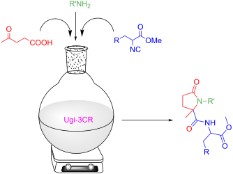
- acid, aromatic and aliphatic amines and amino acid-based isocyanides. First of all, racemic α-amino acids such as DL-tryptophan, DL-phenylalanine and DL-leucine were used as amine source for the synthesis of isocyanide esters 3 through three sequential reactions [30][31]. The first reaction is

Graphical Abstract

Scheme 1: Synthesis of amino acid-based isocyanides starting from α-amino acids.

Scheme 2: Synthesis of pseudo-peptides using levulinic acid, isocyanide esters and amines.
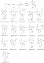
Figure 1: Synthesis of functionalized 5-membered lactams using Ugi reaction. aIsolated yield for mixture of d...

Scheme 3: Proposed mechanism for Ugi-4C-3CR.

Figure 2: ORTEP representation of compound (R*,S*)-4a with thermal ellipsoids at 50% probability. Opposite en...
Syntheses and chemical properties of β-nicotinamide riboside and its analogues and derivatives
- Mikhail V. Makarov and
- Marie E. Migaud
Beilstein J. Org. Chem. 2019, 15, 401–430, doi:10.3762/bjoc.15.36
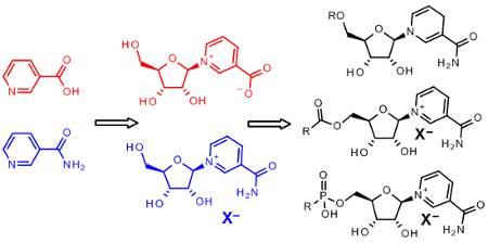

Graphical Abstract

Figure 1: Structural formulas of Nam, NA, NR+, NMN, and NAD+.

Figure 2: Main synthetic routes to nicotinamide riboside (NR+X−).
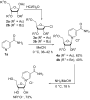
Scheme 1: Synthesis of NR+Cl− based on the reaction of peracylated chlorosugars with Nam.

Figure 3: Predominant formation of β-anomer over α-anomer of NR+X−.

Scheme 2: Synthesis of NR+Cl− by reacting 3,5-di-O-benzoyl-D-ribofuranosyl chloride (5) with Nam (1a).

Figure 4: Mechanism of the formation of the β-anomer of the glycosylated product in the case of the reaction ...
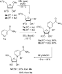
Scheme 3: Synthesis of NR+Br− by reacting bromosugars with Nam (1a).

Scheme 4: Synthesis of NR+OTf− based on the glycosylation of Nam (1a) with tetra-O-acetyl-β-D-ribofuranose (2a...

Scheme 5: Improved synthesis of NR+OTfˉ and NAR+OTfˉ based on the glycosylation of pre-silylated Nam or NA wi...

Scheme 6: Synthesis of triacetylated NAR+OTf− by glycosylation of nicotinic acid trimethylsilyl ester with te...

Scheme 7: Synthesis of NR+Cl− from NR+OTf− by means of ion exchange with sodium chloride solution.

Scheme 8: Synthesis of acylated NR+OTf− by means of ion exchange with sodium chloride.

Scheme 9: Synthesis of triacetylated derivatives of NAR+ by glycosylation of nicotinic acid esters with ribos...

Scheme 10: Synthesis of NR+OTf− from the triflate salt of ethyl nicotinate-2,3,5-triacetyl-β-D-riboside in met...

Scheme 11: Reaction of 2,3,5-tri-O-acetyl-β-phenyl nicotinate riboside triflate salt with secondary and tertia...

Scheme 12: Synthesis of NMN based on the Zincke reaction of N-(2,4-dinitrophenyl)-3-carbamoylpyridinium chlori...

Scheme 13: Synthesis of NMN based on the Zincke reaction of N-(2,4-dinitrophenyl)-3-carbamoylpyridinium chlori...

Scheme 14: Efficacious protection of 2′,3′-hydroxy groups of NR+X−.

Scheme 15: Protection of the 2′,3′-hydroxy groups of NR+Cl– with a mesitylmethylene acetal group.

Figure 5: Reduction of derivatives of NR+Xˉ into corresponding 1,2-; 1,4-; 1,6-NRH derivatives.

Figure 6: Mechanism of the reduction of the pyridinium core with dithionite as adapted from [67].

Scheme 16: Reduction of triacylated NR+OTf– derivatives by sodium dithionite followed by complete removal of a...

Figure 7: Structural formulas of iridium and rhodium catalysts (a)–(d) for regeneration of NAD(P)H from NAD(P)...

Figure 8: Two approaches to synthesis of 5′-derivatives of NR+.

Scheme 17: Synthesis of NMN starting from NR+ salt.

Scheme 18: Efficient synthesis of NMN by phosphorylation of 2′,3′-O-isopropylidene-NR+ triflate followed by re...
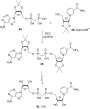
Scheme 19: Synthesis of a bisphosphonate analogue of β-NAD+ based on DCC-induced conjugation of 2′,3′-O-isopro...

Scheme 20: Synthesis of 5′-acyl and 2′,3′,5′-triacyl derivatives of NR+.

Figure 9: Structural formulas of NMN analogues 39–41.
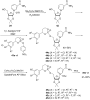
Scheme 21: Synthesis of 5′-phosphorylated derivatives of NR+ using a “reduction–modification–oxidation” approa...

Scheme 22: Synthesis of 5′-phosphorylated derivatives of NR+ using a “reduction–modification–reoxidation” appr...

Figure 10: Structural formulas of 5′-phosphorylated derivatives of NR+.

Scheme 23: Synthesis of 5′-phosphorylated derivatives of NR+ using a direct NR+ phosphorylation approach.

Figure 11: Structural formulas of amino acid NR+ conjugates.

Scheme 24: Synthesis of amino acid NR+ conjugates using NRH and protected amino acid under CDI-coupling condit...

Figure 12: Chemical structures of known isotopically labelled NR+ analogues and derivatives.

Scheme 25: Synthesis of [2′-3H]-NR+ and [2′-3H]-NMN.

Scheme 26: Synthesis of α- and β-anomers of [1′-2H]-NMN.
New standards for collecting and fitting steady state kinetic data
- Kenneth A. Johnson
Beilstein J. Org. Chem. 2019, 15, 16–29, doi:10.3762/bjoc.15.2
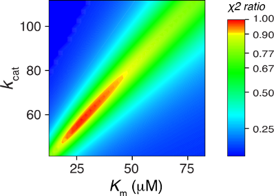
- to determine when titrating with a known concentration of a substrate analog [13]. In addition, many proteins show a change in fluorescence (tyrosine and tryptophan residues) upon substrate binding, affording accurate measurements of the stoichiometry and dissociation constant for binding from an

Graphical Abstract

Figure 1: Michaelis–Menten plot. The rate of product formation is plotted versus substrate concentration and ...
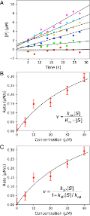
Figure 2: Fitting data to derive kcat and Km. A) Synthetic data were fit to a straight line and then the obse...
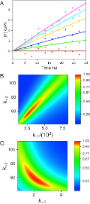
Figure 3: Fitting steady state data by simulation. A) Synthetic data from Figure 2A were fit globally to derive estima...
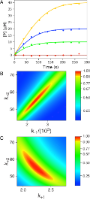
Figure 4: Fitting full progress curve data by simulation. A) Synthetic data were generated and then were fit ...
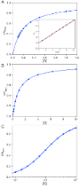
Figure 5: Optimal spacing of data points. Different scenarios for computing the distribution of data points f...
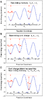
Figure 6: Free energy profiles. Free energy profiles are shown for a three step model with different rate con...

Figure 7: Free energy profile for DNA polymerization. Free energy profiles for a correct base pair (solid blu...
N-Acylated amino acid methyl esters from marine Roseobacter group bacteria
- Hilke Bruns,
- Lisa Ziesche,
- Nargis Khakin Taniwal,
- Laura Wolter,
- Thorsten Brinkhoff,
- Jennifer Herrmann,
- Rolf Müller and
- Stefan Schulz
Beilstein J. Org. Chem. 2018, 14, 2964–2973, doi:10.3762/bjoc.14.276
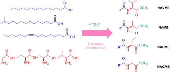
- , tryptophan, arginine, or phenylalanine [30][31][32]. They all carry long chain saturated or unsaturated acyl chains similar to those reported here. Recently, derivatives of the hydrophobic amino acids valine, leucine and isoleucine were also reported [33]. These compounds are produced by a family of acyl

Graphical Abstract

Figure 1: N-Acylhomoserine lactones 1 (Z7-C14:1-AHL) and N-acylalanine methyl esters 2 (Z9-C16:1-NAME) occurr...

Figure 2: Total ion chromatogram (TIC) of an XAD extract of Roseovarius sp. D12_1.68. AHLs, NAMEs and related...

Scheme 1: Synthesis of iso-C15:0-NAME (6). DMAP: 4-dimethylaminopyridine, EDC: 1-ethyl-3-(3-dimethylaminoprop...

Figure 3: Mass spectrum of natural compound D, N-(13-methyltetradecanoyl)alanine methyl ester (iso-C15:0-NAME...
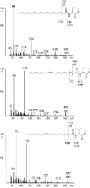
Figure 4: Mass spectra of natural compounds a) K (7, C16:0-NABME), b) J (8, C16:1-NABME), and c) N (9, C16:1-...

Scheme 2: Synthesis of N-acylated amino acid methyl esters 7–11. AAME: amino acid methyl ester.

Figure 5: TIC of an XAD extract of Loktanella sp. F14. Compound S is a minor component within the broad peak.
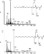
Figure 6: Mass spectra of natural compounds a) R (11, C16:1-NAGME) and b) S (10, C16:0-NAGME).

Figure 7: EI mass spectrometric fragmentation of N-acylated amino acid derivatives. The ions w–z allow identi...
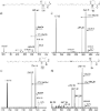
Figure 8: MS2 spectra in ESI positive mode of a) Z9-16OH-C16:1-NAME with [M + H − H2O]+ 356, b) Z9-C16:1-NABM...
Targeting the Pseudomonas quinolone signal quorum sensing system for the discovery of novel anti-infective pathoblockers
- Christian Schütz and
- Martin Empting
Beilstein J. Org. Chem. 2018, 14, 2627–2645, doi:10.3762/bjoc.14.241
- kynurenine pathway starting from tryptophan or by anthranilate synthases from the PqsR-controlled phnAB operon starting using chorismic acid as a source [24]. Either way, the ligase PqsA starts PQS synthesis by condensing anthranilic acid with coenzyme A [25]. The resulting activated thioester (anthraniloyl

Graphical Abstract

Figure 1: The four quorum sensing systems in P. aeruginosa las, iqs, rhl, and pqs. Abbreviations: OdDHL, N-(3...

Figure 2: Schematic overview of the PQS biosynthesis and involvement of related metabolites and PqsE in virul...

Figure 3: Anthranilic acid (1) and derivatives thereof (2–4).

Figure 4: Crystal structure of 6-FABA-AMP in complex with PqsA.

Figure 5: Structures of substrate mimetic PqsA inhibitors.

Figure 6: Structures and characteristics of prominent classes of PqsD inhibitors.

Figure 7: Comparison of docking poses of three prototypic PqsD inhibitors: benzamidobenzoic acid derivative 12...

Figure 8: Structures and characteristics of hits against PqsD identified through different methods.

Figure 9: HHQ and PQS analogues as PqsD inhibitors and chemical probe used for screening.

Figure 10: Structure of PqsD-targeting biofilm inhibitor derived from linezolid.

Figure 11: Fragment-based PqsE-inhibitors 24–26.

Figure 12: PqsE co-crystal structures. (A) native product 2-ABA; (B–D) hit fragments 24–26.

Figure 13: Structurally diverse PqsBC-inhibitors 27–30.

Figure 14: Native PqsR ligand HHQ (31) which is converted into PQS (32) by PqsH and synthetic inhibitors 33 an...

Figure 15: Quinazolinone inhibitor 36 (QZN).

Figure 16: Crystal structure of QZN (36) in complex with PqsRCBD.

Figure 17: Structures of best fitting compounds 37–40 obtained from docking studies.

Figure 18: Initial hit 21 and optimized compound 42 (M64).

Figure 19: Co-crystal structure of M64 (42) with PqsRLBD.

Figure 20: M64 (42) as the starting point for further optimization leading to 43, which was further modified a...

Figure 21: Hit fragments from the benzamide (47–48) and oxadiazole class (49–51).

Figure 22: Structures of dual inhibitors 52–55.

Figure 23: Sulfonyl pyrimidines 56–58 acting as dual PqsD/PqsR inhibitors.
Synthesis and photophysical studies of a multivalent photoreactive RuII-calix[4]arene complex bearing RGD-containing cyclopentapeptides
- Sofia Kajouj,
- Lionel Marcelis,
- Alice Mattiuzzi,
- Adrien Grassin,
- Damien Dufour,
- Pierre Van Antwerpen,
- Didier Boturyn,
- Eric Defrancq,
- Mathieu Surin,
- Julien De Winter,
- Pascal Gerbaux,
- Ivan Jabin and
- Cécile Moucheron
Beilstein J. Org. Chem. 2018, 14, 1758–1768, doi:10.3762/bjoc.14.150
- DNA or the tryptophan (Trp) amino acid residue through a photoinduced electron-transfer (PET) process [16][17][18][19]. Interestingly, the two radical species generated by this PET can recombine to form a covalent photoadduct [20][21][22]. When this photoadduct is formed with the guanine base, the

Graphical Abstract

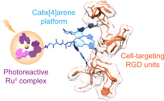
Figure 1: Targeted multivalent phototherapeutic agent and its calix[4]arene-based precursor. RGD = Arg–Gly–As...

Scheme 1: Synthesis of RuII-calix[4]arene complex 7.

Scheme 2: Synthesis of RuII-calix[4]arene-[c-(RGDfK)]4 conjugate 9.
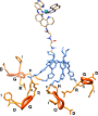
Figure 2: MD snapshot showing an optimized model of conjugate 9. RGDfK units are depicted in orange ribbons, ...

Figure 3: Absorption and emission spectra of RuII-calix[4]arene-[c-(RGDfK)]4 conjugate 9 in water.

Figure 4: Luminescence intensity and excited state lifetime of conjugate 9 in the presence of GMP measured in...
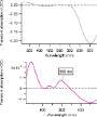
Figure 5: Transient absorption spectra of RuII-calix[4]arene-[c-(RGDfK)]4 conjugate 9 (in 10 mM Tris·HCl buff...

Figure 6: MALDI–MS analysis of a solution containing conjugate 9 and GMP after continuous light irradiation. ...
Carbohydrate inhibitors of cholera toxin
- Vajinder Kumar and
- W. Bruce Turnbull
Beilstein J. Org. Chem. 2018, 14, 484–498, doi:10.3762/bjoc.14.34
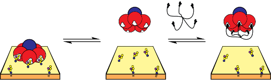
- lactose-2-aminothiazoline conjugate as a CT antagonist. Its affinity for CTB was determined by monitoring the change in fluorescence of tryptophan-88, located in the GM1 binding site, upon titration of the protein with the inhibitor. Compound 6 showed excellent binding with a Kd value of 23 µM [41
- tryptophan fluorescence quenching assay to show that octavalent lactose-based dendrimer 34 (Figure 16) had a Kd value of 33 µM as compared to monovalent lactose derivative having a Kd value of 18,000 µM [51]. Hence, compound 34 displayed 545 fold more potency per lactose unit than monovalent lactose. In

Graphical Abstract

Figure 1: a) Ribbon and b) surface depictions of the cholera toxin: A11 domain in light blue; A12 domain in d...
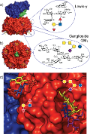
Figure 2: a) Structure of the cholera toxin showing the location of its carbohydrate binding sites and the st...
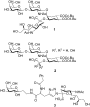
Figure 3: Bernardi and co-workers’ designed oligosaccharide mimetics of GM1.

Figure 4: Structure of monomeric ligands. X = amino acid residues, aminoalkyl, 1,2,3 triazoles; n = 1, 2; R =...

Figure 5: Bivalent inhibitor designed and synthesised by Pickens et al.

Figure 6: Bivalent inhibitor designed and synthesized by Arosio et al.

Figure 7: Bivalent inhibitors designed and synthesised by Leaver and Liu.

Figure 8: Bivalent and tetravalent inhibitor designed and synthesised by Pieters, and Bernardi et al.
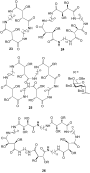
Figure 9: Cyclic inhibitors synthesised by Kumar et al. for CT.

Figure 10: The star-shaped inhibitors reported by Fan, Hol and co-workers.

Figure 11: Differently sized cyclic decavalent peptide core designed by Zhang et al.

Figure 12: Calix[5]arene core-based pentavalent inhibitor designed by Garcia-Hartjes et al.

Figure 13: Corannulene core-based pentavalent inhibitor designed by Mattarella et al.

Figure 14: Pentavalent inhibitor designed by Pieters and co-workers.

Figure 15: Neoglycoprotein inhibitor based on a non-binding mutant of CTB.

Figure 16: Octavalent inhibitor designed by Pieters, Bernardi and co-workers.
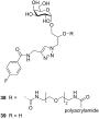
Figure 17: Hetero-bifunctional inhibitor designed by Bundle and co-workers.

Figure 18: Glycopolymers with exchangeable sugar ligands and variable length linkers.
Position-dependent impact of hexafluoroleucine and trifluoroisoleucine on protease digestion
- Susanne Huhmann,
- Anne-Katrin Stegemann,
- Kristin Folmert,
- Damian Klemczak,
- Johann Moschner,
- Michelle Kube and
- Beate Koksch
Beilstein J. Org. Chem. 2017, 13, 2869–2882, doi:10.3762/bjoc.13.279
- assay [30]. Substitution of tryptophan, tyrosine, and phenylalanine residues in a glycosylation-deficient mutant of Candida antarctica lipase B, CalB N74D, by their monofluorinated analogues, left the resistance to proteolytic degradation by proteinase K unchanged [31]. Incorporation of α-fluoroalkyl
- phenylalanine, tyrosine, tryptophan, and leucine in the P1 position. Secondary hydrolysis also occurs at the carbonyl end of isoleucine, methionine, serine, threonine, valine, histidine, glycine, and alanine [47][58][59][60]. The S2 subsite of α-chymotrypsin generally prefers to accommodate hydrophobic residues

Graphical Abstract

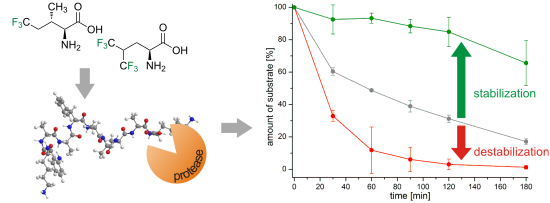
Figure 1: (a) Structures of isoleucine (1), leucine (2), and their fluorinated analogues 5,5,5-trifluoroisole...

Figure 2: Percentage of substrate remaining after incubation for 120 min (left) and 24 h (right) with α-chymo...

Figure 3: Cleavage positions observed in the digestion of library peptides with α-chymotrypsin.

Figure 4: Percentage of substrate remaining after incubation for 120 min (left) and 24 h (right) with pepsin ...

Figure 5: Cleavage positions for digestion of the different peptides with pepsin.

Figure 6: Percentage of substrate remaining after incubation for 120 min (left) and 24 h (right) with elastas...

Figure 7: Cleavage positions for digestion of the different peptides with elastase.

Figure 8: Percentage of substrate remaining after incubation for 120 min (left) and 24 h (right) with protein...

Figure 9: Cleavage positions found with proteinase K.

Figure 10: Dimension of stabilization or destabilization upon TfIle or HfLeu incorporation compared to the non...
Synthesis of 1,3-cis-disubstituted sterically encumbered imidazolidinone organocatalysts
- Jan Wallbaum and
- Daniel B. Werz
Beilstein J. Org. Chem. 2017, 13, 2577–2583, doi:10.3762/bjoc.13.254
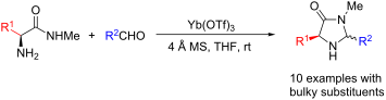
- -tryptophan-derived methyl amides 9b and 9c were converted in good yields to the corresponding imidazolidinones (Table 1, entries 2 and 3). In the case of 7c it is important to use not more than 1.0 equivalent of the aldehyde, otherwise a further reaction with the indole moiety is observed. A significant
- , 343.1529. (2S,5S)-5-((Indol-3-yl)methyl)-3-methyl-2-(naphthalen-1-yl)imidazolidin-4-one (7c). (S)-Tryptophan methyl amide (340 mg, 1.56 mmol, 1.0 equiv), 1-naphthyl carbaldehyde (243 mg, 212 µL, 1.56 mmol, 1.0 equiv), 4 Å molecular sieves (160 mg) and Yb(OTf)3 (97.0 mg, 156 µmol, 10 mol %) in THF (8.0 mL

Graphical Abstract

Scheme 1: a) MacMillan’s enantioselective α-alkylation of aldehydes. b) Our enantioselective 1,3-chlorosulfen...
A concise flow synthesis of indole-3-carboxylic ester and its derivatisation to an auxin mimic
- Marcus Baumann,
- Ian R. Baxendale and
- Fabien Deplante
Beilstein J. Org. Chem. 2017, 13, 2549–2560, doi:10.3762/bjoc.13.251
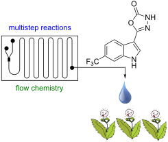
- chemistry; heterocycle; hydrogenation; indole; multistep; Introduction Indoles are amongst the most important bioactive heterocyclic structures being commonly encountered in the amino acid tryptophan (1), the related neurotransmitter serotonin (2) as well as numerous complex alkaloid natural products and

Graphical Abstract

Figure 1: Natural indole containing molecules 1–7 of biological importance and synthetic auxin analogue 8 req...

Scheme 1: Synthetic strategy towards desired indole product 8.

Scheme 2: Initial flow reactor setup for the synthesis of intermediate 11.

Scheme 3: Coflore ACR setup for the synthesis of intermediate 11.

Scheme 4: Quenching and work-up of the reaction stream from the Coflore ACR for the synthesis intermediate 11....

Figure 2: X-ray structure of intermediate 11, and reductive cyclisation products 12 and 14, assigned structur...

Scheme 5: Stepwise reduction of intermediate 11 under hydrogenation conditions. * Indicates potential tautome...

Scheme 6: Flow sequence for the construction of product 8.

Scheme 7: Assembled process for flow synthesis of product 8 with yields and throughputs.
Asymmetric synthesis of propargylamines as amino acid surrogates in peptidomimetics
- Matthias Wünsch,
- David Schröder,
- Tanja Fröhr,
- Lisa Teichmann,
- Sebastian Hedwig,
- Nils Janson,
- Clara Belu,
- Jasmin Simon,
- Shari Heidemeyer,
- Philipp Holtkamp,
- Jens Rudlof,
- Lennard Klemme,
- Alessa Hinzmann,
- Beate Neumann,
- Hans-Georg Stammler and
- Norbert Sewald
Beilstein J. Org. Chem. 2017, 13, 2428–2441, doi:10.3762/bjoc.13.240
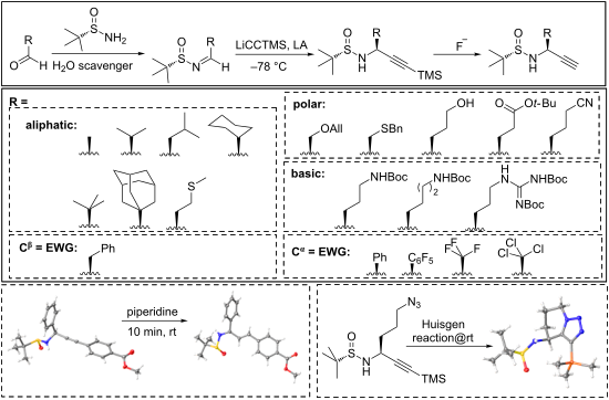
- % [21]. Synthesis of propargylamines containing electron-withdrawing substituents Aromatic and carbonyl substituents in the Cβ-position of propargylamines (occurring in analogoues of the amino acids phenylalanine, tyrosine, histidine, tryptophan, aspartic acid and asparagine) increase the acidity of the
- imine 5h) after desilylation with TBAF (Table 2). As the benzylic proton of sulfinylimine 5h is quite acidic, approach II was not pursued for the synthesis of propargylamines analogous to tyrosine, histidine, tryptophan, and aspartate. Proteinogenic amino acids do not contain substituents, which

Graphical Abstract

Figure 1: Concept of carboxylic acid or amide bond replacement on the basis of an alkyne moiety.

Figure 2: Selection of reactions based on propargylamines as precursors. a) Intramolecular Pauson–Khand react...

Figure 3: Two different approaches for the stereoselective de novo synthesis of propargylamines using Ellman’...

Figure 4: Synthesis of propargylamines 4a and 4b by introducing the side chain as nucleophile. (a) HC≡CCH2OH,...

Figure 5: Reaction of N-sulfinylimine 5h with (trimethylsilyl)ethynyllithium. (a) GP-3 or GP-4. (b) Aqueous w...

Figure 6: Side reactions observed in the course of the conversion of highly electrophilic sulfinylimines 5. (...

Figure 7: a) Possible transition states TI and TII for the transfer of the methyl moiety from AlMe3 to the im...

Figure 8: Base-induced rearrangement of propargylamines bearing electron-withdrawing substituents.

Figure 9: Base-catalyzed rearrangement of propargylamines 11 to α,β-unsaturated imines 12. A) Reaction scheme...
Conjugated nitrosoalkenes as Michael acceptors in carbon–carbon bond forming reactions: a review and perspective
- Yaroslav D. Boyko,
- Valentin S. Dorokhov,
- Alexey Yu. Sukhorukov and
- Sema L. Ioffe
Beilstein J. Org. Chem. 2017, 13, 2214–2234, doi:10.3762/bjoc.13.220
- Ottenheijm in the total synthesis of an analogue of the tryptophan-containing natural alkaloid neoechinulin B (indole 77) [67][68] (Scheme 28). At the initial stage, N-methylindole was alkylated with ethyl bromopyruvate oxime and sodium carbonate to give adduct 78, which was then transformed into N

Graphical Abstract

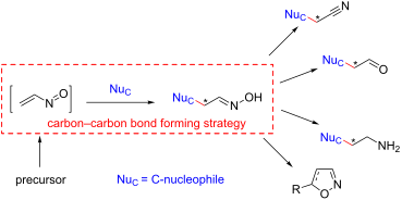
Scheme 1: Precursors of nitrosoalkenes NSA.

Scheme 2: Reactions of cyclic α-chlorooximes 1 with 1,3-dicarbonyl compounds.

Scheme 3: C-C-coupling of N,N-bis(silyloxy)enamines 3 with 1,3-dicarbonyl compounds.

Scheme 4: Reaction of N,N-bis(silyloxy)enamines 3 with nitronate anions.

Scheme 5: Reaction of α-chlorooximes TBS ethers 2 with ester enolates.

Scheme 6: Assembly of bicyclooctanone 14 via an intramolecular cyclization of nitrosoalkene NSA2.

Scheme 7: A general strategy for the assembly of bicyclo[2.2.1]heptanes via an intramolecular cyclization of ...

Scheme 8: Stereochemistry of Michael addition to cyclic nitrosoalkene NSA3.

Scheme 9: Stereochemistry of Michael addition to acyclic nitrosoalkenes NSA4.

Scheme 10: Stereochemistry of Michael addition to γ-alkoxy nitrosoalkene NSA5.

Scheme 11: Oppolzer’s total synthesis of 3-methoxy-9β-estra(1,3,5(10))trien(11,17)dione (25).

Scheme 12: Oppolzer’s total synthesis of (+/−)-isocomene.

Figure 1: Alkaloids synthesized using stereoselective Michael addition to conjugated nitrosoalkenes.

Scheme 13: Weinreb’s total synthesis of alstilobanines A, E and angustilodine.

Scheme 14: Weinreb’s approach to the core structure of apparicine alkaloids.

Scheme 15: Weinreb’s synthesis of (+/−)-myrioneurinol via stereoselective conjugate addition of malonate to ni...

Scheme 16: Reactions of cyclic α-chloro oximes with Grignard reagents.

Scheme 17: Corey’s synthesis of (+/−)-perhydrohistrionicotoxin.

Scheme 18: Addition of Gilman’s reagents to α,β-epoxy oximes 53.

Scheme 19: Addition of Gilman’s reagents to α-chlorooximes.

Scheme 20: Reaction of silyl nitronate 58 with organolithium reagents via nitrosoalkene NSA12.

Scheme 21: Reaction of β-ketoxime sulfones 61 and 63 with lithium acetylides.

Scheme 22: Electrophilic addition of nitrosoalkenes NSA14 to electron-rich arenes.

Scheme 23: Addition of nitrosoalkenes NSA14 to pyrroles and indoles.

Scheme 24: Reaction of phosphinyl nitrosoalkenes NSA15 with indole.

Scheme 25: Reaction of pyrrole with α,α’-dihalooximes 70.

Scheme 26: Synthesis of indole-derived psammaplin A analogue 72.

Scheme 27: Synthesis of tryptophanes by reduction of oximinoalkylated indoles 68.

Scheme 28: Ottenheijm’s synthesis of neoechinulin B analogue 77.

Scheme 29: Synthesis of 1,2-dihydropyrrolizinones 82 via addition of pyrrole to ethyl bromopyruvate oxime.

Scheme 30: Kozikowski’s strategy to indolactam-based alkaloids via addition of indoles to ethyl bromopyruvate ...

Scheme 31: Addition of cyanide anion to nitrosoalkenes and subsequent cyclization to 5-aminoisoxazoles 86.

Scheme 32: Et3N-catalysed addition of trimethylsilyl cyanide to N,N-bis(silyloxy)enamines 3 leading to 5-amino...

Scheme 33: Addition of TMSCN to allenyl N-siloxysulfonamide 89.

Scheme 34: Reaction of nitrosoallenes NSA16 with malodinitrile and ethyl cyanoacetic ester.

Scheme 35: [4 + 1]-Annulation of nitrosoalkenes NSA with sulfonium ylides 92.

Scheme 36: Reaction of diazo compounds 96 with nitrosoalkenes NSA.

Scheme 37: Tandem Michael addition/oxidative cyclization strategy to isoxazolines 100.
Oxidative dehydrogenation of C–C and C–N bonds: A convenient approach to access diverse (dihydro)heteroaromatic compounds
- Santanu Hati,
- Ulrike Holzgrabe and
- Subhabrata Sen
Beilstein J. Org. Chem. 2017, 13, 1670–1692, doi:10.3762/bjoc.13.162
- tryptophan derivatives with appropriate aldehydes. A hypervalent iodine reagent, iodobenzene diacetate was used in stoichiometric quantities to facilitate both oxidative decarboxylation/dehydrogenation of 108–110 to afford the desired natural products 111–113 (Scheme 42). Conclusion Substantial amount of

Graphical Abstract

Figure 1: Representative bioactive heterocycles.

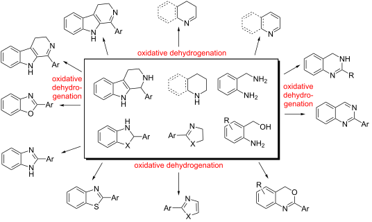
Scheme 1: The concept of oxidative dehydrogenation.
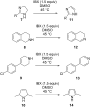
Scheme 2: IBX-mediated oxidative dehydrogenation of various heterocycles [31-34].

Scheme 3: Potential mechanism of IBX-mediated oxidative dehydrogenation of N-heterocycles [31-34].

Scheme 4: IBX-mediated room temperature one-pot condensation–oxidative dehydrogenation of o-aminobenzylamines....
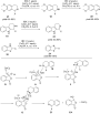
Scheme 5: Anhydrous cerium chloride-catalyzed, IBX-mediated oxidative dehydrogenation of various heterocycles...

Scheme 6: Oxidative dehydrogenation of quinazolinones with I2 and DDQ [37-40].

Scheme 7: DDQ-mediated oxidative dehydrogenation of thiazolidines and oxazolidines.

Scheme 8: Oxone-mediated oxidative dehydrogenation of intermediates from o-phenylenediamine and o-aminobenzyl...

Scheme 9: Transition metal-free oxidative cross-dehydrogenative coupling.

Scheme 10: NaOCl-mediated oxidative dehydrogenation.

Scheme 11: NBS-mediated oxidative dehydrogenation of tetrahydro-β-carbolines.

Scheme 12: One-pot synthesis of various methyl(hetero)arenes from o-aminobenzamide in presence of di-tert-buty...

Scheme 13: Oxidative dehydrogenation of 1, 4-DHPs.

Scheme 14: Synthesis of quinazolines in the presence of MnO2.

Scheme 15: Selenium dioxide and potassium dichromate-mediated oxidative dehydrogenation of tetrahydro-β-carbol...

Scheme 16: Synthesis of substituted benzazoles in the presence of barium permanganate.
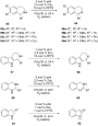
Scheme 17: Oxidative dehydrogenation with phenanthroline-based catalysts. PPTS = pyridinium p-toluenesulfonic ...

Scheme 18: Oxidative dehydrogenation with Flavin mimics.

Scheme 19: o-Quinone based bioinspired catalysts for the synthesis of dihydroisoquinolines.

Scheme 20: Cobalt-catalyzed aerobic dehydrogenation of Hantzch 1,4-DHPs and pyrazolines.

Scheme 21: Mechanism of cobalt-catalyzed aerobic dehydrogenation of Hantzch 1,4-DHPs.

Scheme 22: DABCO and TEMPO-catalyzed aerobic oxidative dehydrogenation of quinazolines and 4H-3,1-benzoxazines....

Scheme 23: Putative mechanism for Cu(I)–DABCO–TEMPO catalyzed aerobic oxidative dehydrogenation of tetrahydroq...

Scheme 24: Potassium triphosphate modified Pd/C catalysts for the oxidative dehydrogenation of tetrahydroisoqu...

Scheme 25: Ruthenium-catalyzed polycyclic heteroarenes.

Scheme 26: Plausible mechanism of the ruthenium-catalyzed dehydrogenation.

Scheme 27: Bi-metallic platinum/iridium alloyed nanoclusters and 5,5’,6,6’-tetrahydroxy-3,3,3’,3’-tetramethyl-...

Scheme 28: Magnesium iodide-catalyzed synthesis of quinazolines.

Scheme 29: Ferrous chloride-catalyzed aerobic dehydrogenation of 1,2,3,4-tetrahydroquinolines.

Scheme 30: Cu(I)-catalyzed oxidative aromatization of indoles.

Scheme 31: Putative mechanism of the transformation.

Scheme 32: Oxidative dehydrogenation of pyrimidinones and pyrimidines.
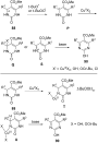
Scheme 33: Putative mechanisms (radical and metal-catalyzed) of the transformation.

Scheme 34: Ferric chloride-catalyzed, TBHP-oxidized synthesis of substituted quinazolinones and arylquinazolin...

Scheme 35: Iridium-catalyzed oxidative dehydrogenation of quinolines.

Scheme 36: Microwave-assisted synthesis of β-carboline with a catalytic amount of Pd/C in lithium carbonate at...

Scheme 37: 4-Methoxy-TEMPO-catalyzed aerobic oxidative synthesis of 2-substituted benzazoles.

Scheme 38: Plausible mechanism of the 4-methoxy-TEMPO-catalyzed transformation.

Scheme 39: One-pot synthesis of 2-arylquinazolines, catalyzed by 4-hydroxy-TEMPO.

Scheme 40: Oxidative dehydrogenation – a key step in the synthesis of AZD8926.

Scheme 41: Catalytic oxidative dehydrogenation of tetrahydroquinolines to afford bioactive molecules.

Scheme 42: Iodobenzene diacetate-mediated synthesis of β-carboline natural products.
Molecular recognition of N-acetyltryptophan enantiomers by β-cyclodextrin
- Spyros D. Chatziefthimiou,
- Mario Inclán,
- Petros Giastas,
- Athanasios Papakyriakou,
- Konstantina Yannakopoulou and
- Irene M. Mavridis
Beilstein J. Org. Chem. 2017, 13, 1572–1582, doi:10.3762/bjoc.13.157
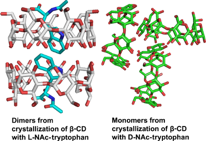
- expected to have restricted mobility and limited disorder. Indicative of the interest and possible applications of the CD use in chiral selectivity/discrimination of tryptophan are studies in aqueous solution [21], in electrochemistry for sensor development [17][22][23], as components of solid phases in
- complexation (Supporting Information File 1, Figure S1). The inflection point of the graphs at 0.5 indicates a 1:1 stoichiometry for both enantiomers. The tryptophan protons were affected differently upon complexation (Supporting Information File 1, Figure S2), i.e., the graphs due to shifts of the indole’s
- orientation of the guest inside the host and the formation of the crystals per se. Experimental Materials and methods N-Acetyl-L-tryptophan (L-NAcTrp), N-acetyl-D-tryptophan (D-NAcTrp) and β-CD were obtained from Sigma-Aldrich. Deuterium oxide was a product of Deutero GmbH. NMR spectroscopy The spectra were

Graphical Abstract

Scheme 1: Numbering scheme of one glucopyranose residue (G) of β-CD and the NAcTrp molecule; specific atom la...

Figure 1: 3D maps of the observed dipolar, through-space host–guest interactions depicted so as to (a) reflec...
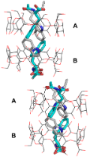
Figure 2: Two dimers of β-CD–L-NAcTrp, stacked along the a-axis, are shown. Each β-CD dimer (A, B) encloses a...

Figure 3: β-CD–L-NAcTrp complex at the interface between two β-CD dimers along the a-axis (major orientation ...

Figure 4: “β-CD–D-NAcTrp” structure. (a) The herring bone packing of β-CD along the c-axis; (b) The guest (cy...

Figure 5: L-NAcTrp and L-NAcPhe in β-CD dimers (the lines indicate the levels of the O2 and O3 secondary hydr...
Conformational study of L-methionine and L-cysteine derivatives through quantum chemical calculations and 3JHH coupling constant analyses
- Weslley G. D. P. Silva,
- Carolyne B. Braga and
- Roberto Rittner
Beilstein J. Org. Chem. 2017, 13, 925–937, doi:10.3762/bjoc.13.94
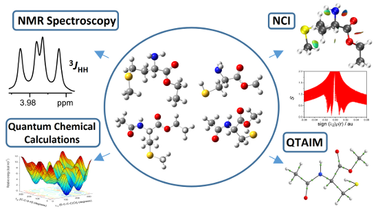
- derivatives of tryptophan [20], phenylalanine and tyrosine [21], aspartic acid [22], proline [23] and histidine [24]. These studies have provided significant results to understand the importance of the corresponding amino acids in processes in which they take part in the polypeptide chain. Furthermore, these

Graphical Abstract

Figure 1: Most stable conformers of 1 and 2 obtained theoretically at the ωB97X-D/aug-cc-pVTZ level.

Figure 2: Three possible dispositions presented by geometries of the analyzed compounds 1−4.

Figure 3: Most stable conformers of 3 and 4 obtained theoretically at the ωB97X-D/aug-cc-pVTZ level.
Figure 4: (a) QTAIM molecular graphs [30]; (b) NCI isosurfaces generated with S = 0.6 au and blue−green−red scali...

Figure 5: (a) QTAIM molecular graphs; (b) NCI isosurfaces generated with S = 0.6 au and blue−green−red scalin...

Figure 6: Definition of the selected dihedral angles for the studied compounds.
Opportunities and challenges for the sustainable production of structurally complex diterpenoids in recombinant microbial systems
- Katarina Kemper,
- Max Hirte,
- Markus Reinbold,
- Monika Fuchs and
- Thomas Brück
Beilstein J. Org. Chem. 2017, 13, 845–854, doi:10.3762/bjoc.13.85
- insights into cyclization mechanism but also lead to novel products or changes in the product spectra. This has also been demonstrated for the bacterial diterpene cyclooctat-9-en-7-ol synthase (CotB2) [57], also a putative Class I TPS. Mutation of tryptophan 288 to glycine in CotB2 resulted in the

Graphical Abstract

Scheme 1: Isoprenoid biosynthetic pathways and examples for their engineering in heterologous production syst...

Scheme 2: Mutational engineering of different classes of terpene synthases. Left side: The natural product of...
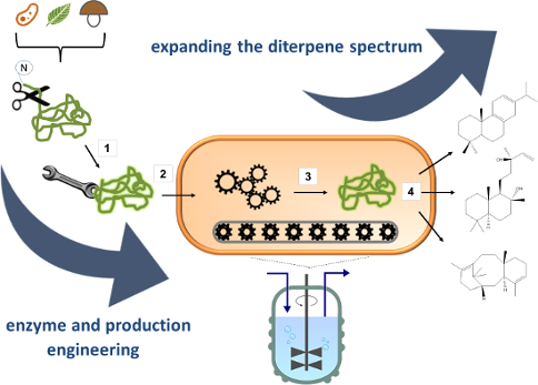
Figure 1: Implementation of a microbial cell factory. 1: Selection of enzymes from different species. P450 an...
Fluorescent carbon dots from mono- and polysaccharides: synthesis, properties and applications
- Stephen Hill and
- M. Carmen Galan
Beilstein J. Org. Chem. 2017, 13, 675–693, doi:10.3762/bjoc.13.67
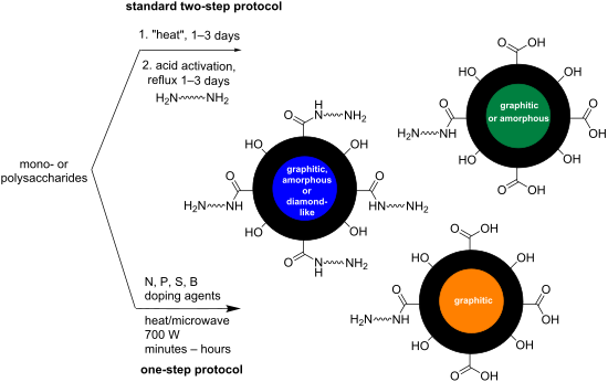
- overlap with the cell autofluorescence. Recent years have seen an increase in synthetic reports of large scale N-doped CDs with good QYs from carbohydrate starting materials. For example in 2014, Leitão et al. described the microwave synthesis of CDs using 2.5 g of glucose and 0.3 g of tryptophan as the N
- properties are only observed below a diameter of 10 nm, which is not the case here and has since been observed in one other carbohydrate-derived CD synthesis [34]. The team demonstrated the utility of the glucose/tryptophan-derived CDs as a sensor of peroxynitrite anions (NO3−) in solution. The peroxynitrite
- traditionally difficult to detect. The team was able to show significant quenching of the CDs via tryptophan oxidation of the exposed residues on the surface of CDs (Scheme 5). Post-oxidation fluorescence is compromised and therefore can be used as a signal for selectively sensing peroxynitrite up to

Graphical Abstract

Scheme 1: Microwave-driven reaction of glucose in the presence of PEG-200 to afford blue-emissive CDs.

Scheme 2: Two-step synthesis of TTDDA-coated CDs generated from acid-refluxed glucose.

Scheme 3: Glucose-derived CDs using KH2PO4 as a dehydrating agent to both form and tune CD’s properties.

Scheme 4: Ultrasonic-mediated synthesis of glucose-derived CDs in the presence of ammonia.

Scheme 5: Tryptophan-derived CDs used for the sensing of peroxynitrite in serum-fortified cell media.

Scheme 6: Glucose-derived CDs conjugated with methotrexate for the treatment of H157 lung cancer cells.

Scheme 7: Boron-doped blue-emissive CDs used for sensing of Fe3+ ion in solution.

Scheme 8: N/S-doped CDs with aggregation-induced fluorescence turn-off to temperature and pH stimuli.

Scheme 9: N/P-doped hollow CDs for efficient drug delivery of doxorubicin.

Scheme 10: N/P-doped CDs applied to the sensing of Fe3+ ions in mammalian T24 cells.

Scheme 11: Comparative study of CDs formed from glucose and N-doped with TTDDA and dopamine.

Scheme 12: Formation of blue-emissive CDs from the microwave irradiation of glycerol, TTDDA and phosphate.

Scheme 13: Xylitol-derived N-doped CDs with excellent photostability demonstrating the importance of Cl incorp...

Scheme 14: Base-mediated synthesis of CDs with nanocrystalline cores, from fructose and maltose, without forci...

Scheme 15: N/P-doped green-emissive CDs working in tandem with hyaluronic acid-coated AuNPs to monitor hyaluro...

Scheme 16: Three-minute microwave synthesis of Cl/N-doped CDs from glucosamine hydrochloride and TTDDA to affo...

Scheme 17: Mechanism for the formation of N/Cl-doped CDs via key aldehyde and iminium intermediates, monitored...

Scheme 18: Phosphoric acid-mediated synthesis of orange-red emissive CDs from sucrose.

Scheme 19: Proposed HMF dimer, and its formation mechanism, that upon aggregations bestows orange-red emissive...

Scheme 20: Different polysaccharide-derived CDs in the presence of PEG-200 and how the starting material compo...

Scheme 21: Tetracycline release profiles for differentially-decorated CDs.

Scheme 22: Hyaluronic acid (HA) and glycine-derived CDs, suspected to be decorated in unreacted HA, allowing r...

Scheme 23: Cyclodextrin-derived CDs used for detection of Ag+ ions in solution, based on the formal reduction ...

Scheme 24: Cyclodextrin and OEI-derived CDs, coated with hyaluronic acid and DOX, to produce an effective lung...

Scheme 25: Cellulose and urea-derived N-doped CDs with green-emissive fluorescence.
Posttranslational isoprenylation of tryptophan in bacteria
- Masahiro Okada,
- Tomotoshi Sugita and
- Ikuro Abe
Beilstein J. Org. Chem. 2017, 13, 338–346, doi:10.3762/bjoc.13.37
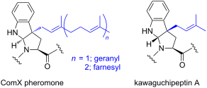
- the thiol groups of proteins in eukaryotes. In contrast, the Bacillus quorum sensing peptide pheromone, the ComX pheromone, possesses a posttranslationally modified tryptophan residue, and the tryptophan residue is isoprenylated with either a geranyl or farnesyl group at the gamma position to form a
- tricyclic skeleton that bears a newly formed pyrrolidine, similar to proline. The post-translational dimethylallylation of two tryptophan residues of a cyclic peptide, kawaguchipeptin A, from cyanobacteria has also been reported. Interestingly, the modified tryptophan residues of kawaguchipeptin A have the
- same scaffold as that of the ComX pheromones, but with the opposite stereochemistry. This review highlights the biosynthetic pathways and posttranslational isoprenylation of tryptophan. In particular, recent studies on peptide modifying enzymes are discussed. Keywords: Bacillus subtilis

Graphical Abstract
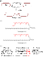
Figure 1: (A) Schematic representation of pheromone-induced conjugation tube formation for mating in Tremella...

Figure 2: Chemical structures of (A) surfactin A and (B) poly-γ-glutamic acid.
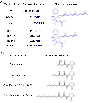
Figure 3: (A) Two types of posttranslational isoprenylations of ComX variants. The modified tryptophan residu...

Figure 4: (A) Schematic representation of the signal transduction cascade of quorum sensing stimulated by the...

Figure 5: Amino acid sequences of ComX from seven Bacillus strains. The sequences of the mature pheromones ar...
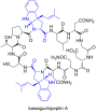
Figure 6: Chemical structure of kawaguchipeptin A. Dimethylallylated tryptophan residues are colored blue.
Phosphated cyclodextrins as water-soluble chiral NMR solvating agents for cationic compounds
- Cira Mollings Puentes and
- Thomas J. Wenzel
Beilstein J. Org. Chem. 2017, 13, 43–53, doi:10.3762/bjoc.13.6
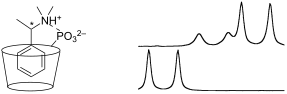
- -indanol (23), tryptophan (24), tryptophan methyl ester (25), 1-methyltryptophan methyl ester (26), 1-(1-naphthyl)ethylamine (27), N,N-dimethyl-1-(1-naphthyl)ethylamine (28), propranolol (29), pheniramine (30), brompheniramine (31), doxylamine (32), and carbinoxamine (33) (Figure 2) in their protonated

Graphical Abstract

Figure 1: Structure of cyclodextrins (CD) and their carboxymethylated (CM-CD) and phosphated (P-CD) derivativ...
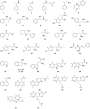
Figure 2: Structures of substrates included in the study. All compounds were examined in their protonated for...

Figure 3: The (a) C-methyl resonance of 3 (10 mM, enriched in the (R)-enantiomer) in the presence of (b) P-α-...

Figure 4: The (a) methine resonance of the carbinol carbon (5.124 ppm) and N-methyl resonance (2.768 ppm) of 7...

Figure 5: The N-methyl resonance of 7 (10 mM, enriched in (1S,2R)-enantiomer) with P-β-CD-LDS (20 mM) and con...
Interactions between cyclodextrins and cellular components: Towards greener medical applications?
- Loïc Leclercq
Beilstein J. Org. Chem. 2016, 12, 2644–2662, doi:10.3762/bjoc.12.261
- ., alanine, valine, leucine, isoleucine, proline, phenylalanine, tryptophan, cysteine and methionine), they can be easily included inside the CDs. This complexation leads to modification of the protein. For sake of clarity, only some typical examples are reported in this section. In their paper on the
- whereas the opposite is true for the Me-α-CD. It should be noted that the thermal stability reduction is very important for G1-β-CD. Based on fluorescence spectroscopy, the authors suggested that CDs include the side chains of tryptophan (Trp) residues of lysozyme within their internal cavities to
- NMR signals corresponding to Trp residues were shifted upon the addition of G1-β-CD due to encapsulation of the tryptophan residues in the G1-β-CD cavity [92]. In addition, the 1H NMR signals for cysteine 64 and isoleucine 98 were also influenced to a considerable extent with the addition of G1-β-CD

Graphical Abstract

Scheme 1: Structure and conventional representation of native CDs.

Scheme 2: Proposed mechanism for morphological changes in erythrocytes induced by methylated CDs.

Scheme 3: Proposed mechanism for the conformational change of egg white lysozyme with temperature elevating i...

Scheme 4: Sugar hydrophobicity scale according to Janado and Yano and correlation with the binding constant v...

Scheme 5: Principle of chemically switched DNA intercalators based on anthryl(alkylamino)-β-CD/1-adamantanol ...

Scheme 6: Normal (left) and diseased artery (right).

Scheme 7: Kinetics of [DiC10] insertion into the viral envelope without (left) or with γ-CD (right). Note tha...
Rearrangements of organic peroxides and related processes
- Ivan A. Yaremenko,
- Vera A. Vil’,
- Dmitry V. Demchuk and
- Alexander O. Terent’ev
Beilstein J. Org. Chem. 2016, 12, 1647–1748, doi:10.3762/bjoc.12.162

Graphical Abstract
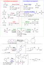
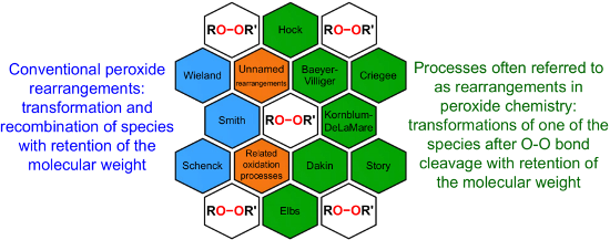
Figure 1: The named transformations considered in this review.

Scheme 1: The Baeyer–Villiger oxidation.

Scheme 2: The general mechanism of the peracid-promoted Baeyer–Villiger oxidation.

Scheme 3: General mechanism of the Lewis acid-catalyzed Baeyer–Villiger rearrangement.

Scheme 4: The theoretically studied mechanism of the BV oxidation reaction promoted by H2O2 and the Lewis aci...

Scheme 5: Proton movements in the transition states of the Baeyer–Villiger oxidation.

Scheme 6: The dependence of the course of the Baeyer–Villiger oxidation on the type of O–O-bond cleavage in t...
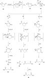
Scheme 7: The acid-catalyzed Baeyer–Villiger oxidation of cyclic epoxy ketones 22.

Scheme 8: Oxidation of isophorone oxide 29.

Scheme 9: Synthesis of acyl phosphate 32 from acyl phosphonate 31.

Scheme 10: Synthesis of aflatoxin B2 (36).

Scheme 11: The Baeyer–Villiger rearrangement of ketones 37 to lactones 38.

Scheme 12: Synthesis of 3,4-dimethoxybenzoic acid (40) via Baeyer–Villiger oxidation.

Scheme 13: Oxone transforms α,β-unsaturated ketones 43 into vinyl acetates 44.

Scheme 14: The Baeyer–Villiger oxidation of ketones 45 using diaryl diselenide and hydrogen peroxide.

Scheme 15: Baeyer–Villiger oxidation of (E)-2-methylenecyclobutanones.

Scheme 16: Oxidation of β-ionone (56) by H2O2/(BnSe)2 with formation of (E)-2-(2,6,6-trimethylcyclohex-1-en-1-...

Scheme 17: The mechanism of oxidation of ketones 58a–f by hydrogen peroxide in the presence of arsonated polys...

Scheme 18: Oxidation of ketone (58b) by H2O2 to 6-methylcaprolactone (59b) catalyzed by Pt complex 66·BF4.

Scheme 19: Oxidation of ketones 67 with H2O2 in the presence of [(dppb}Pt(µ-OH)]22+.

Scheme 20: The mechanism of oxidation of ketones 67 in the presence of [(dppb}Pt(µ-OH)]22+ and H2O2.

Scheme 21: Oxidation of benzaldehydes 69 in the presence of the H2O2/MeReO3 system.

Scheme 22: Oxidation of acetophenones 72 in the presence of the H2O2/MeReO3 system.

Scheme 23: Baeyer–Villiger oxidation of 2-adamantanone (45c) in the presence of Sn-containing mesoporous silic...

Scheme 24: Aerobic Baeyer–Villiger oxidation of ketones 76 using metal-free carbon.

Scheme 25: A regioselective Baeyer-Villiger oxidation of functionalized cyclohexenones 78 into a dihydrooxepin...

Scheme 26: The oxidation of aldehydes and ketones 80 by H2O2 catalyzed by Co4HP2Mo15V3O62.

Scheme 27: The cleavage of ketones 82 with hydrogen peroxide in alkaline solution.

Scheme 28: Oxidation of ketones 85 to esters 86 with H2O2–urea in the presence of KHCO3.

Scheme 29: Mechanism of the asymmetric oxidation of cyclopentane-1,2-dione 87a with the Ti(OiPr)4/(+)DET/t-BuO...

Scheme 30: The oxidation of cis-4-tert-butyl-2-fluorocyclohexanone (93) with m-chloroperbenzoic acid.

Scheme 31: The mechanism of the asymmetric oxidation of 3-substituted cyclobutanone 96a in the presence of chi...

Scheme 32: Enantioselective Baeyer–Villiger oxidation of cyclic ketones 98.

Scheme 33: Regio- and enantioselective Baeyer–Villiger oxidation of cyclic ketones 101.

Scheme 34: The proposed mechanism of the Baeyer–Villiger oxidation of acetal 105f.

Scheme 35: Synthesis of hydroxy-10H-acridin-9-one 117 from tetramethoxyanthracene 114.

Scheme 36: The Baeyer–Villiger oxidation of the fully substituted pyrrole 120.

Scheme 37: The Criegee rearrangement.

Scheme 38: The mechanism of the Criegee reaction of a peracid with a tertiary alcohol 122.

Scheme 39: Criegee rearrangement of decaline ethylperoxoate 127 into ketal 128.

Scheme 40: The ionic cleavage of 2-methoxy-2-propyl perester 129.

Scheme 41: The Criegee rearrangement of α-methoxy hydroperoxide 136.
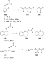
Scheme 42: Synthesis of enol esters and acetals via the Criegee rearrangement.

Scheme 43: Proposed mechanism of the transformation of 1-hydroperoxy-2-oxabicycloalkanones 147a–d.

Scheme 44: Transformation of 3-hydroxy-1,2-dioxolanes 151 into diketone derivatives 152.

Scheme 45: Criegee rearrangement of peroxide 153 with the mono-, di-, and tri-O-insertion.

Scheme 46: The sequential Criegee rearrangements of adamantanes 157a,b.

Scheme 47: Synthesis of diaryl carbonates 160a–d from triarylmethanols 159a–d through successive oxygen insert...

Scheme 48: The synthesis of sesquiterpenes 162 from ketone 161 with a Criegee rearrangement as one key step.

Scheme 49: Synthesis of trans-hydrindan derivatives 164, 165.

Scheme 50: The Hock rearrangement.

Scheme 51: The general scheme of the cumene process.

Scheme 52: The Hock rearrangement of aliphatic hydroperoxides.
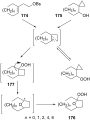
Scheme 53: The mechanism of solvolysis of brosylates 174a–c and spiro cyclopropyl carbinols 175a–c in THF/H2O2....

Scheme 54: The fragmentation mechanism of hydroperoxy acetals 178 to esters 179.

Scheme 55: The acid-catalyzed rearrangement of phenylcyclopentyl hydroperoxide 181.

Scheme 56: The peroxidation of tertiary alcohols in the presence of a catalytic amount of acid.

Scheme 57: The acid-catalyzed reaction of bicyclic secondary alcohols 192 with hydrogen peroxide.

Scheme 58: The photooxidation of 5,6-disubstituted 3,4-dihydro-2H-pyrans 196.

Scheme 59: The oxidation of tertiary alcohols 200a–g, 203a,b, and 206.

Scheme 60: Transformation of functional peroxide 209 leading to 2,3-disubstitued furans 210 in one step.

Scheme 61: The synthesis of carbazoles 213 via peroxide rearrangement.

Scheme 62: The construction of C–N bonds using the Hock rearrangement.

Scheme 63: The synthesis of moiety 218 from 217 which is a structural motif in the antitumor–antibiotic of CC-...

Scheme 64: The in vivo oxidation steps of cholesterol (219) by singlet oxygen.

Scheme 65: The proposed mechanism of the rearrangement of cholesterol-5α-OOH 220.

Scheme 66: Photochemical route to artemisinin via Hock rearrangement of 223.

Scheme 67: The Kornblum–DeLaMare rearrangement.

Scheme 68: Kornblum–DeLaMare transformation of 1-phenylethyl tert-butyl peroxide (225).

Scheme 69: The synthesis 4-hydroxyenones 230 from peroxide 229.

Scheme 70: The Kornblum–DeLaMare rearrangement of peroxide 232.

Scheme 71: The reduction of peroxide 234.

Scheme 72: The Kornblum–DeLaMare rearrangement of endoperoxide 236.

Scheme 73: The rearrangement of peroxide 238 under Kornblum–DeLaMare conditions.

Scheme 74: The proposed mechanism of rearrangement of peroxide 238.

Scheme 75: The Kornblum–DeLaMare rearrangement of peroxides 242a,b.

Scheme 76: The base-catalyzed rearrangements of bicyclic endoperoxides having electron-withdrawing substituent...

Scheme 77: The base-catalyzed rearrangements of bicyclic endoperoxides 249a,b having electron-donating substit...

Scheme 78: The base-catalyzed rearrangements of bridge-head substituted bicyclic endoperoxides 251a,b.

Scheme 79: The Kornblum–DeLaMare rearrangement of hydroperoxide 253.

Scheme 80: Synthesis of β-hydroxy hydroperoxide 254 from endoperoxide 253.

Scheme 81: The amine-catalyzed rearrangement of bicyclic endoperoxide 263.

Scheme 82: The base-catalyzed rearrangement of meso-endoperoxide 268 into 269.

Scheme 83: The photooxidation of 271 and subsequent Kornblum–DeLaMare reaction.

Scheme 84: The Kornblum–DeLaMare rearrangement as one step in the oxidation reaction of enamines.

Scheme 85: The Kornblum–DeLaMare rearrangement of 3,5-dihydro-1,2-dioxenes 284, 1,2-dioxanes 286, and tert-but...

Scheme 86: The Kornblum–DeLaMare rearrangement of epoxy dioxanes 290a–d.

Scheme 87: Rearrangement of prostaglandin H2 292.

Scheme 88: The synthesis of epicoccin G (297).

Scheme 89: The Kornblum–DeLaMare rearrangement used in the synthesis of phomactin A.

Scheme 90: The Kornblum–DeLaMare rearrangement in the synthesis of 3H-quinazolin-4-one 303.

Scheme 91: The Kornblum–DeLaMare rearrangement in the synthesis of dolabriferol (308).

Scheme 92: Sequential transformation of 3-substituted 2-pyridones 309 into 3-hydroxypyridine-2,6-diones 311 in...

Scheme 93: The Kornblum–DeLaMare rearrangement of peroxide 312 into hydroxy enone 313.

Scheme 94: The Kornblum–DeLaMare rearrangement in the synthesis of polyfunctionalized carbonyl compounds 317.

Scheme 95: The Kornblum–DeLaMare rearrangement in the synthesis of (Z)-β-perfluoroalkylenaminones 320.

Scheme 96: The Kornblum–DeLaMare rearrangement in the synthesis of γ-ketoester 322.

Scheme 97: The Kornblum–DeLaMare rearrangement in the synthesis of diterpenoids 326 and 328.

Scheme 98: The synthesis of natural products hainanolidol (331) and harringtonolide (332) from peroxide 329.

Scheme 99: The synthesis of trans-fused butyrolactones 339 and 340.

Scheme 100: The synthesis of leucosceptroid C (343) and leucosceptroid P (344) via the Kornblum–DeLaMare rearra...

Scheme 101: The Dakin oxidation of arylaldehydes or acetophenones.

Scheme 102: The mechanism of the Dakin oxidation.

Scheme 103: A solvent-free Dakin reaction of aromatic aldehydes 356.

Scheme 104: The organocatalytic Dakin oxidation of electron-rich arylaldehydes 358.

Scheme 105: The Dakin oxidation of electron-rich arylaldehydes 361.

Scheme 106: The Dakin oxidation of arylaldehydes 358 in water extract of banana (WEB).

Scheme 107: A one-pot approach towards indolo[2,1-b]quinazolines 364 from indole-3-carbaldehydes 363 through th...

Scheme 108: The synthesis of phenols 367a–c from benzaldehydes 366a-c via acid-catalyzed Dakin oxidation.

Scheme 109: Possible transformation paths of the highly polarized boric acid coordinated H2O2–aldehyde adduct 3...

Scheme 110: The Elbs oxidation of phenols 375 to hydroquinones.

Scheme 111: The mechanism of the Elbs persulfate oxidation of phenols 375 affording p-hydroquinones 376.

Scheme 112: Oxidation of 2-pyridones 380 under Elbs persulfate oxidation conditions.

Scheme 113: Synthesis of 3-hydroxy-4-pyridone (384) via an Elbs oxidation of 4-pyridone (382).

Scheme 114: The Schenck rearrangement.

Scheme 115: The Smith rearrangement.

Scheme 116: Three main pathways of the Schenck rearrangement.

Scheme 117: The isomerization of hydroperoxides 388 and 389.

Scheme 118: Trapping of dioxacyclopentyl radical 392 by oxygen.

Scheme 119: The hypothetical mechanism of the Schenck rearrangement of peroxide 394.

Scheme 120: The autoxidation of oleic acid (397) with the use of labeled isotope 18O2.

Scheme 121: The rearrangement of 18O-labeled hydroperoxide 400 under an atmosphere of 16O2.

Scheme 122: The rearrangement of the oleate-derived allylic hydroperoxides (S)-421 and (R)-425.

Scheme 123: Mechanisms of Schenck and Smith rearrangements.

Scheme 124: The rearrangement and cyclization of 433.

Scheme 125: The Wieland rearrangement.

Scheme 126: The rearrangement of bis(triphenylsilyl) 439 or bis(triphenylgermyl) 441 peroxides.

Scheme 127: The oxidative transformation of cyclic ketones.

Scheme 128: The hydroxylation of cyclohexene (447) in the presence of tungstic acid.

Scheme 129: The oxidation of cyclohexene (447) under the action of hydrogen peroxide.

Scheme 130: The reaction of butenylacetylacetone 455 with hydrogen peroxide.

Scheme 131: The oxidation of bridged 1,2,4,5-tetraoxanes.

Scheme 132: The proposed mechanism for the oxidation of bridged 1,2,4,5-tetraoxanes.

Scheme 133: The rearrangement of ozonides.

Scheme 134: The acid-catalyzed oxidative rearrangement of malondialdehydes 462 under the action of H2O2.
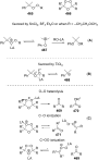
Scheme 135: Pathways of the Lewis acid-catalyzed cleavage of dialkyl peroxides 465 and ozonides 466.

Scheme 136: The mechanism of the transformation of (tert-butyldioxy)cyclohexanedienones 472.

Scheme 137: The synthesis of Vitamin K3 from 472a.

Scheme 138: Proposed mechanism for the transformation of 478d into silylated endoperoxide 479d.

Scheme 139: The rearrangement of hydroperoxide 485 to form diketone 486.

Scheme 140: The base-catalyzed rearrangement of cyclic peroxides 488a–g.

Scheme 141: Synthesis of chiral epoxides and aldols from peroxy hemiketals 491.

Scheme 142: The multistep transformation of (R)-carvone (494) to endoperoxides 496a–e.

Scheme 143: The decomposition of anthracene endoperoxide 499.

Scheme 144: Synthesis of esters 503 from aldehydes 501 via rearrangement of peroxides 502.

Scheme 145: Two possible paths for the base-promoted decomposition of α-azidoperoxides 502.

Scheme 146: The Story decomposition of cyclic diperoxide 506a.

Scheme 147: The Story decomposition of cyclic triperoxide 506b.

Scheme 148: The thermal rearrangement of endoperoxides A into diepoxides B.

Scheme 149: The transformation of peroxide 510 in the synthesis of stemolide (511).

Scheme 150: The possible mechanism of the rearrangement of endoperoxide 261g.

Scheme 151: The photooxidation of indene 517.

Scheme 152: The isomerization of ascaridole (523).

Scheme 153: The isomerization of peroxide 525.

Scheme 154: The thermal transformation of endoperoxide 355.

Scheme 155: The photooxidation of cyclopentadiene (529) at a temperature higher than 0 °C.

Scheme 156: The thermal rearrangement of endoperoxides 538a,b.

Scheme 157: The transformation of peroxides 541.

Scheme 158: The thermal rearrangements of strained cyclic peroxides.

Scheme 159: The thermal rearrangement of diacyl peroxide 551 in the synthesis of C4-epi-lomaiviticin B core 553....

Scheme 160: The 1O2 oxidation of tryptophan (554) and rearrangement of dioxetane intermediate 555.

Scheme 161: The Fe(II)-promoted cleavage of aryl-substituted bicyclic peroxides.

Scheme 162: The proposed mechanism of the Fe(II)-promoted rearrangement of 557a–c.

Scheme 163: The reaction of dioxolane 563 with Fe(II) sulfate.

Scheme 164: Fe(II)-promoted rearrangement of 1,2-dioxane 565.

Scheme 165: Fe(II) cysteinate-promoted rearrangement of 1,2-dioxolane 568.

Scheme 166: The transformation of 1,2-dioxanes 572a–c under the action of FeCl2.

Scheme 167: Fe(II) cysteinate-promoted transformation of tetraoxane 574.

Scheme 168: The CoTPP-catalyzed transformation of bicyclic endoperoxides 600a–d.

Scheme 169: The CoTPP-catalyzed transformation of epoxy-1,2-dioxanes.

Scheme 170: The Ru(II)-catalyzed reactions of 1,4-endoperoxide 261g.

Scheme 171: The Ru(II)-catalyzed transformation as a key step in the synthesis of elyiapyrone A (610) from 1,4-...

Scheme 172: Peroxides with antimalarial activity.

Scheme 173: The interaction of iron ions with artemisinin (616).

Scheme 174: The interaction of FeCl2 with 1,2-dioxanes 623, 624.

Scheme 175: The mechanism of reaction 623 and 624 with Fe(II)Cl2.

Scheme 176: The reaction of bicyclic natural endoperoxides G3-factors 631–633 with FeSO4.

Scheme 177: The transformation of terpene cardamom peroxide 639.
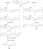
Scheme 178: The different ways of the cleavage of tetraoxane 643.

Scheme 179: The LC–MS analysis of interaction of tetraoxane 646 with iron(II)heme 647.

Scheme 180: The rearrangement of 3,6-epidioxy-1,10-bisaboladiene (EDBD, 649).

Scheme 181: Easily oxidized substrates.

Scheme 182: Biopathway of synthesis of prostaglandins.

Scheme 183: The reduction and rearrangements of isoprostanes.

Scheme 184: The partial mechanism for linoleate 658 oxidation.

Scheme 185: The transformation of lipid hydroperoxide.

Scheme 186: The acid-catalyzed cleavage of the product from free-radical oxidation of cholesterol (667).

Scheme 187: Two pathways of catechols oxidation.

Scheme 188: Criegee-like or Hock-like rearrangement of the intermediate hydroperoxide 675 in dioxygenase enzyme...

Scheme 189: Carotinoides 679 cleavage by carotenoid cleavage dioxygenases.
Cyclisation mechanisms in the biosynthesis of ribosomally synthesised and post-translationally modified peptides
- Andrew W. Truman
Beilstein J. Org. Chem. 2016, 12, 1250–1268, doi:10.3762/bjoc.12.120
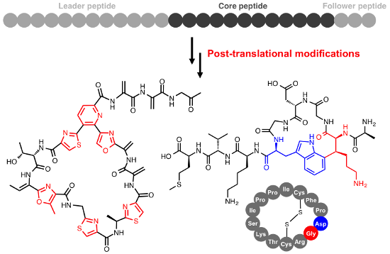
- streptococcal RiPP that is involved in bacterial communication [127]. Here, StrB catalyses the formation of a carbon–carbon bond between lysine and tryptophan side chains [25]. This is proposed to be mechanistically similar to thioether bond formation, although the role of the second [4Fe–4S] cluster is likely
- to differ slightly as it is unlikely that either carbon initially bonds to this cluster (Figure 10B). Instead, a radical on the lysine β-carbon (generated by 5’-dA• hydrogen abstraction) attacks C-7 on the tryptophan ring. This generates an indolyl radical that can lose an electron to the second [4Fe
- candidate enzymes. A number of these cyclisations are found in partially characterised pathways, such as the S–C cross-link in α-amanitin (Figure 8B) that is formed between cysteine and tryptophan residues (the tryptathionine linkage [131]). The ComQXPA quorum sensing (QS) system [132] found in Bacillus

Graphical Abstract

Figure 1: Schematic of RiPP biosynthesis. Thiazole/oxazole formation is represented by the blue heterocycle (...

Figure 2: Examples of heterocycles in RiPPs alongside the precursor peptides that these molecules derive from...

Figure 3: Formation of thiazoles and oxazoles in RiPPs. A) Biosynthesis of microcin B17. B) Mechanistic model...

Figure 4: Lanthionine bond formation. A) Nisin and its precursor peptide. B) Mechanism of lanthionine bond fo...

Figure 5: S-[(Z)-2-Aminovinyl]-D-cysteine (AviCys) formation in the epidermin pathway. A) Mechanisms for deca...
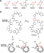
Figure 6: Cyclisation in the biosynthesis of thiopeptides. A) Mechanism of TclM-catalysed heterocyclisation i...

Figure 7: ATP-dependent macrocyclisation. A) General mechanism for ATP-dependent macrolactonisation or macrol...

Figure 8: Peptidase-like macrolactam formation. A) General mechanism. B) Examples of RiPPs cyclised by serine...

Figure 9: Structure of autoinducing peptide AIP-I from Staphylococcus aureus and the sequence of the correspo...
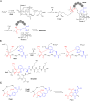
Figure 10: Radical cyclisation in RiPP biosynthesis. A) AlbA-catalysed formation of thioethers in the biosynth...

Figure 11: RiPPs with uncharacterised mechanisms of cyclisation. Unusual heterocycles in ComX and methanobacti...
Conjugate addition–enantioselective protonation reactions
- James P. Phelan and
- Jonathan A. Ellman
Beilstein J. Org. Chem. 2016, 12, 1203–1228, doi:10.3762/bjoc.12.116
- the major enantiomer was not defined (Scheme 3) [18]. Indium was used to initiate the addition of a perfluorobutyl radical to α-aminoacrylate 11 followed by hydrogen atom transfer to the resulting α-amino α-ester radical from (R,R)-12. Enantioenriched tryptophan derivatives are useful building blocks

Graphical Abstract

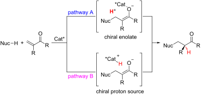
Figure 1: Two general pathways for conjugate addition followed by enantioselective protonation.

Scheme 1: Tomioka’s enantioselective addition of arylthiols to α-substituted acrylates.

Scheme 2: Sibi’s enantioselective hydrogen atom transfer reactions.

Scheme 3: Mikami’s addition of perfluorobutyl radical to α-aminoacrylate 11.

Scheme 4: Reisman’s Friedel–Crafts conjugate addition–enantioselective protonation approach toward tryptophan...

Scheme 5: Pracejus’s enantioselective addition of benzylmercaptan to α-aminoacrylate 20.

Scheme 6: Kumar and Dike’s enantioselective addition of thiophenol to α-arylacrylates.

Scheme 7: Tan’s enantioselective addition of aromatic thiols to 2-phthalimidoacrylates.

Scheme 8: Glorius’ enantioselective Stetter reactions with α-substituted acrylates.

Scheme 9: Dixon’s enantioselective addition of thiols to α-substituted acrylates.

Figure 2: Chiral phosphorous ligands.

Scheme 10: Enantioselective addition of arylboronic acids to methyl α-acetamidoacrylate.

Scheme 11: Frost’s enantioselective additions to dimethyl itaconate.

Scheme 12: Darses and Genet’s addition of potassium organotrifluoroborates to α-aminoacrylates.

Scheme 13: Proposed mechanism for enantioselective additions to α-aminoacrylates.

Scheme 14: Sibi’s addition of arylboronic acids to α-methylaminoacrylates.

Scheme 15: Frost’s enantioselective synthesis of α,α-dibenzylacetates 64.

Scheme 16: Rovis’s hydroheteroarylation of α-substituted acrylates with benzoxazoles.

Scheme 17: Proposed mechanism for the hydroheteroarylation of α-substituted acrylates with benzoxazoles.
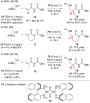
Scheme 18: Sodeoka’s enantioselective addition of amines to N-benzyloxycarbonyl acrylamides 75 and 77.

Scheme 19: Proposed catalytic cycle for Sodeoka’s enantioselective addition of amines.

Scheme 20: Sibi’s enantioselective Friedel–Crafts addition of pyrroles to imides 84.

Scheme 21: Kobayashi’s enantioselective addition of malonates to α-substituted N-acryloyloxazolidinones.

Scheme 22: Chen and Wu’s enantioselective addition of thiophenol to N-methacryloyl benzamide.

Scheme 23: Tan’s enantioselective addition of secondary phosphine oxides and thiols to N-arylitaconimides.

Scheme 24: Enantioselective addition of thiols to α-substituted N-acryloylamides.

Scheme 25: Kobayashi’s enantioselective addition of thiols to α,β-unsaturated ketones.

Scheme 26: Feng’s enantioselective addition of pyrazoles to α-substituted vinyl ketones.

Scheme 27: Luo and Cheng’s addition of indoles to vinyl ketones by enamine catalysis.

Scheme 28: Curtin–Hammett controlled enantioselective addition of indole.

Scheme 29: Luo and Cheng’s enantioselective additions to α-branched vinyl ketones.

Scheme 30: Lou’s reduction–conjugate addition–enantioselective protonation.

Scheme 31: Luo and Cheng’s primary amine-catalyzed addition of indoles to α-substituted acroleins.

Scheme 32: Luo and Cheng’s proposed mechanism and transition state.

Figure 3: Shibasaki’s chiral lanthanum and samarium tris(BINOL) catalysts.

Scheme 33: Shibasaki’s enantioselective addition of 4-tert-butyl(thiophenol) to α,β-unsaturated thioesters.

Scheme 34: Shibasaki’s application of chiral (S)-SmNa3tris(binaphthoxide) catalyst 144 to the total synthesis ...

Scheme 35: Shibasaki’s cyanation–enantioselective protonation of N-acylpyrroles.

Scheme 36: Tanaka’s hydroacylation of acrylamides with aliphatic aldehydes.

Scheme 37: Ellman’s enantioselective addition of α-substituted Meldrum’s acids to terminally unsubstituted nit...

Scheme 38: Ellman’s enantioselective addition of thioacids to α,β,β-trisubstituted nitroalkenes.

Scheme 39: Hayashi’s enantioselective hydroarylation of diphenylphosphinylallenes.

Scheme 40: Hayashi’s enantioselective hydroarylation of diphenylphosphinylallenes.

Figure 4: Togni’s chiral ferrocenyl tridentate nickel(II) and palladium(II) complexes.

Scheme 41: Togni’s enantioselective hydrophosphination of methacrylonitrile.

Scheme 42: Togni’s enantioselective hydroamination of methacrylonitrile.
Muraymycin nucleoside-peptide antibiotics: uridine-derived natural products as lead structures for the development of novel antibacterial agents
- Daniel Wiegmann,
- Stefan Koppermann,
- Marius Wirth,
- Giuliana Niro,
- Kristin Leyerer and
- Christian Ducho
Beilstein J. Org. Chem. 2016, 12, 769–795, doi:10.3762/bjoc.12.77
- between F288 and glutamic acid 287 (E287) with the peptide motif arginine-tryptophan-x-x-tryptophan (RWxxW, x represents an arbitrary amino acid) was found. Mutants F288L and E287A showed reduced or no detectable enzyme inhibition, thus indicating a secondary binding site for potential MraY inhibitors

Graphical Abstract
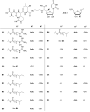
Figure 1: Structures of the naturally occurring muraymycins isolated by McDonald et al. [22].
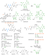
Figure 2: Structures of selected classes of nucleoside antibiotics. Similarities to the muraymycins are highl...

Figure 3: Structure of peptidoglycan. Long chains of glycosides (alternating GlcNAc (green) and MurNAc (blue)...

Figure 4: Schematic representation of bacterial cell wall biosynthesis.
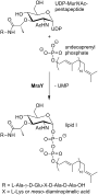
Figure 5: Translocase I (MraY) catalyses the reaction of UDP-MurNAc-pentapeptide with undecaprenyl phosphate ...

Figure 6: Proposed mechanisms for the MraY-catalysed reaction. A: Two-step mechanism postulated by Heydanek e...

Scheme 1: First synthetic access towards simplified muraymycin analogues as reported by Yamashita et al. [76].

Scheme 2: Synthesis of (+)-caprazol (19) reported by Ichikawa, Matsuda et al. [92].
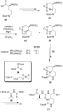
Scheme 3: Synthesis of the epicapreomycidine-containing urea dipeptide via C–H activation [96,97].

Scheme 4: Synthesis of muraymycin D2 and its epimer reported by Ichikawa, Matsuda et al. [96,97].

Scheme 5: Synthesis of the urea tripeptide unit as a building block for muraymycins reported by Kurosu et al. ...

Scheme 6: Synthesis of the uridine-derived core structure of naturally occuring muraymycins reported by Ducho...
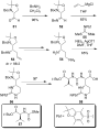
Scheme 7: Synthesis of the epicapreomycidine-containing urea dipeptide from Garner's aldehyde reported by Duc...

Scheme 8: Synthesis of a hydroxyleucine-derived aldehyde building block reported by Ducho et al. [107].

Scheme 9: Synthesis of 5'-deoxy muraymycin C4 (65) as a closely related natural product analogue [78,109,110].

Figure 7: Summary of modifications on semisynthetic muraymycin analogues tested by Lin et al. [86]. Most active c...

Figure 8: Bioactive muraymycin analogues identified by Yamashita et al. [76].
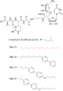
Figure 9: Muraymycin D2 and several non-natural lipidated analogues 91a–d [77,114].
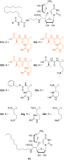
Figure 10: Non-natural muraymycin analogues with varying peptide structures [77,114].

Figure 11: SAR results for several structural variations of the muraymycin scaffold.

Figure 12: Muraymycin analogues designed for potential anti-Pseudomonas activity (most active analogues are hi...
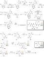
Scheme 10: Proposed outline pathway for muraymycin biosynthesis based on the analysis of the biosynthetic gene...

Scheme 11: Biosynthesis of the nucleoside core structure of A-90289 antibiotics (which is identical to the mur...

Scheme 12: Transaldolase-catalysed formation of the key intermediate GlyU 101 in the biosynthesis of muraymyci...